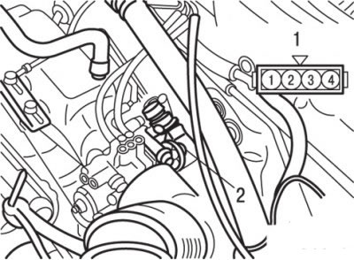
Pic. 7.13. Connector Pin Arrangement (1) and throttle position sensor (2)
2. Measure resistance between pins «1» And «4» connector on the side of the sensor, which should be 3.5–6.5 kOhm (pic. 7.13).
3. Measure resistance between pins «2» And «4» connector on the side of the sensor. When slowly opening the throttle from a fully closed (idling) position to fully open resistance should change smoothly in proportion to the throttle opening angle.
4. If the resistance is out of the range of nominal values or does not change smoothly, then replace the throttle position sensor.
