Removing
To remove, perform the following steps in sequence.
1. Remove the motor protective cover.
2. Relieve fuel pressure (fuel splash prevention).
3. Remove the air filter.
4. Remove the throttle body.
5. Remove the intake manifold.
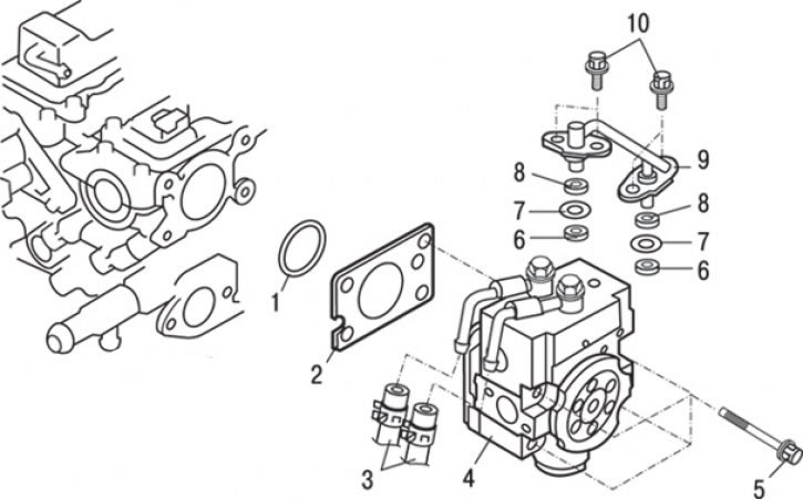
Pic. 8.7. High pressure fuel pump: 1 - ring gasket; 2 - gasket; 3 - connection of fuel return hoses; 4 - high pressure fuel pump; 5 - bolt (5+17 Nm); 6 - support ring «A»; 7 - ring gasket; 8 - support ring «IN»; 9 – fuel tube; 10 - bolt (11–13 Nm)
6. Loosen the clamps and disconnect the fuel return hoses 3 (pic. 8.7).
7. Unscrew the bolts and remove the fuel pipe 9.
8. Remove support rings «A» 6
9. Remove O-rings 7.
10. Remove support rings «IN» 8
11. Unscrew the bolts and remove the high pressure fuel pump 4.
12. Remove O-ring 1.
13. Remove gasket 2.
Installation
Installation is carried out in the reverse order of removal, taking into account the following.
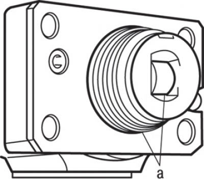
Pic. 8.8. Lubrication points (A) injection pump pusher roller and O-ring
1. Apply a small amount of fresh engine oil to the injection pump tappet roller and O-ring (see fig. 8.8).
2. Install the high pressure fuel pump in the cylinder head at a right angle, tighten the mounting bolts slightly more than by hand. The final tightening of the fastening bolts to the nominal torque is carried out at the final stage.
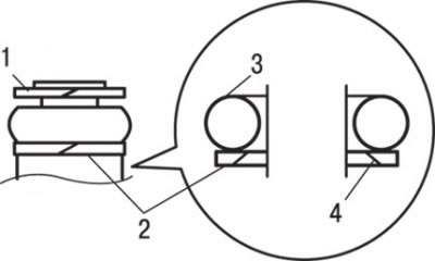
Pic. 8.9. Installation of support rings and gaskets: 1 - support ring «A»; 2 - support ring «IN»; 3 - annular gasket; 4 - beveled surface
3. Install support ring and O-ring as shown in fig. 8.9.
Attention! Install support ring «IN» its beveled surface from the reverse side of the O-ring as shown in Fig. 8.9.
Make sure the support ring is installed correctly «A» (support ring outside diameter «A» equal to 14.8 mm). Do not confuse it with the fuel pressure sensor support ring.
4. Apply a small amount of clean engine oil to the O-ring.
Note. Be careful not to let engine oil get into the high pressure fuel pump housing or into the fuel manifold.
5. Install the fuel pipe into the high pressure fuel pump and into the holes of the fuel manifolds at a right angle. Securely install the fuel pipe without twisting it, and only then tighten the mounting bolts to a torque of 11–13 Nm.
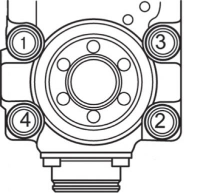
Pic. 8.10. High pressure fuel pump tightening sequence
6. Tighten the pre-fixed high-pressure fuel pump mounting bolts to the torque shown in fig. 8.10 sequences with a torque of 5.0 Nm.
7. Finally tighten bolts of fastening of the fuel pump of a high pressure in specified on fig. 8.10 sequences with a torque of 17 Nm. The difference in the tightening torques of adjacent high pressure fuel pump mounting bolts must not exceed 2 Nm.
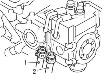
Pic. 8.11. Location of identification marks on fuel return hoses: 1 - white mark; 2 - blue mark
8. Install the fuel return hoses so that the identification marks on them are oriented as shown in fig. 8.11.
Air is removed from the high-pressure fuel line with the engine running at a crankshaft speed of 2000 min-1 for more than 15 s.
Attention! When air enters the high pressure fuel lines during work, a drop in operating pressure in the fuel line will set DTC 56. If diagnostic code No. 56 appears on the display of the MUT-II device due to its registration by the fuel pressure sensor, it must be erased after normal fuel pressure in the system is restored.
9. Install the engine protection cover.
10. Check the tightness of the power system.
11. Install the air filter.
12. Install the throttle body.
13. Install the intake manifold.
