Disassembly
To disassemble the steering mechanism, perform the following operations in sequence.

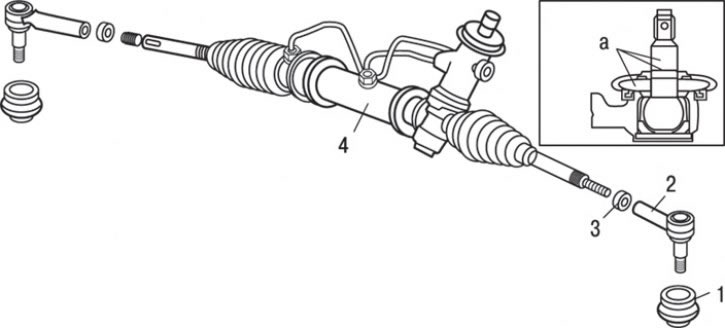
Pic. 13.16. Steering gear: a - places for applying lubrication; 1 - protective cover; 2 – a tip of steering draft; 3 - locknut (42 Nm); 4 - steering gear assembly
1. Remove the tie rod end 2 (pic. 13.16). To do this, first loosen the lock nut 3 of the tip, then unscrew the tip from the steering rod.
2. Loosen the clamps and remove the protective covers 1.
Assembly
Assembly is carried out in the reverse order of removal, taking into account the following.
1. Adjust the total torque required to turn the steering gear by holding the steering gear in a vise.
Attention! When installing the steering gear in a vise, clamp it only at the attachment points. If you clamp the steering gear in other places, you can deform or damage the steering gear housing.
2. Set the rail to the center position. Tighten the rail stop cover to 15 Nm.

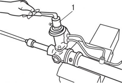
Pic. 13.14. Key usage (1) to check the total torque required to turn the steering gear
3. In the neutral position, turn the gear with a special key clockwise one turn in 4-6 seconds (see fig. 13.14). Unscrew the rack stop cover by 30–60°and adjust the turning torque to the nominal value.
4. To check the total torque required to turn the drive gear, use a special wrench to rotate the steering gear within one revolution for 4-6 seconds (pic. 13.14). The nominal value is 0.6 - 1.3 Nm (deviation - 0.4 Nm).
Attention! In the process of adjustment, try to set the upper limit of the nominal value. Make sure that there are no knocks or jams when moving the rack.
Attention! If adjustment cannot be achieved within the specified angle of rotation of the gear, then check or replace the parts of the stop and rack stop cover.
5. After completing the adjustment, tighten the rack stop cap locknut.
6. Fill the inside of the protective boot with multipurpose grease.
7. Lubricate the sealing lip of the protective boot with 3M ATD No. 8661 sealant.

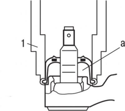
Pic. 13.17. Using a special tool (1) for installation of a protective cover on a finger of a spherical joint of a tip of steering draft and a place (A) applying lubricant
8. Using the special tool, install the protective boot on the ball joint pin of the tie rod end (pic. 13.17).

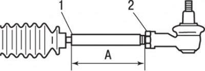
Pic. 13.18. Control dimension for installing the left and right tie rod ends: A = 184.5 mm; 1 - groove for setting the edge of the corrugated cover; 2 - locknut
9. Wrap the left and right tips of steering drafts to the size specified in fig. 13.18, and tighten the locknuts.
