
Measurement method
Install a special sensor on the high voltage wire.
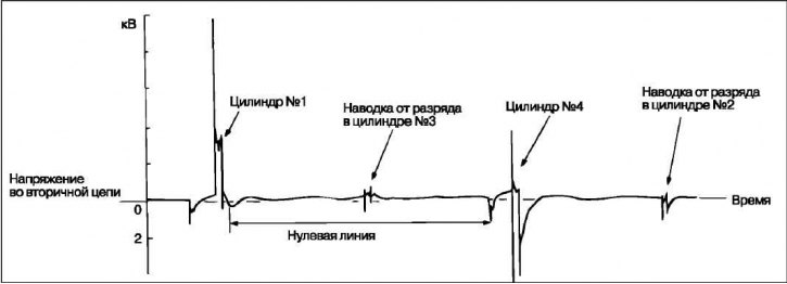
Attention! For cylinders 2 and 4 the breakdown voltage polarity will be opposite to the voltage polarity for cylinders 1 and 3.
Since the ignition system is used with a simultaneous spark discharge in two cylinders, it is possible to simultaneously observe voltage waveforms for two cylinders (for 1 and 4 cyl. and for 2 and 3 cyl.). However, the removal of a high voltage oscillogram is possible only for the cylinder on the wire of which a special sensor is installed.
It can be difficult to determine which cylinder the observed waveform belongs to. It should be remembered that the oscillogram of the cylinder to which the high-voltage sensor is connected will have a more stable image on the screen.
Install a synchronization sensor on the high voltage wire.
Attention! Install the synchronization sensor on the same high-voltage wire on which the special high-voltage sensor is installed.
Oscillogram of the voltage of a working ignition system
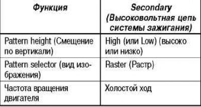
- Conditions under which the measurement is made (only parameter changed «pattern selector» - type of image)
- Pattern selector (image view)
- Display (long display)
Conditions under which the measurement is made

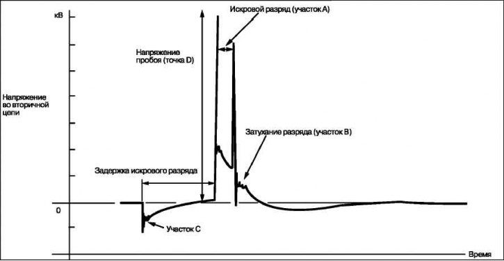
Characteristic areas of the waveform
Section A: amplitude (height), duration and trailing edge of the spark discharge allow you to set the following deviations (See examples of waveforms with characteristic faults - examples 1, 2, 3 and 4).
Plot A

Section B: the number of vibrations in the decay section (See waveform example #5).
Plot B

Segment C: number of oscillations at the beginning of the breakdown voltage growth section (See waveform example #5).
Plot C

Point D: breakdown voltage (as well as the distribution of stress on the cylinders) allows you to establish the following regularities.
Point D

