Removal and installation
− Before starting to remove parts, carry out the following operations:
- A) Extract the refrigerant from the air conditioning system.
- b) Remove the glove box and the engine and CVT control unit.
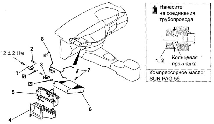
− Removal of parts is carried out in the order of numbers indicated in the figure "Removing the evaporator assembly (manual air conditioner) ".

Removing the evaporator assembly (manual air conditioner). 1 - low pressure hose connection, 2 - tube connection "IN" high pressure, 3 - expansion valve (for sedan models from 10.2001: remove the intermediate air duct seal), 4 - intermediate air duct, 5 - evaporator cover, 6 - evaporator, 7 - evaporator air temperature sensor retainer, 8 - evaporator air temperature sensor.
− When removing parts, pay attention to the following operations:
1. Removing the low pressure hose, tube "IN" high pressure and expansion valve.
Cover the disconnected evaporator tubes and fittings to prevent moisture, dust and other contaminants from entering.
Attention: the hoses must be tight, otherwise the compressor oil and the dryer receiver may be saturated with water vapor from the atmosphere. Do not use porous material to cover pipes and fittings.
2. Removing the evaporator.
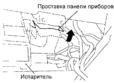
For easy removal of the evaporator, it is necessary to cut the instrument panel spacer as shown in the figure.
Attention: do not cut a through hole in the instrument panel spacer.

− Installation of parts is carried out in the reverse order of removal.
Note: when replacing parts, it is necessary to add compressor oil to the system (see section "Working with the air conditioning system").
− After completing the installation of the parts, perform the following operations:
- A) Install the glove box and the engine and CVT control unit.
- b) Charge the system with coolant.
Checking the evaporator air temperature sensor
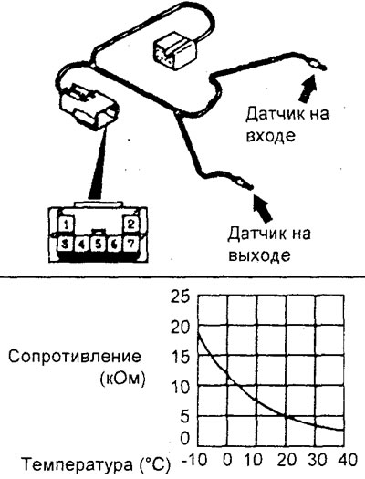
1. Checking the evaporator air temperature sensor (at the entrance).
Measure resistance between leads "1" And "3" connector for two or more temperatures. The resistance between the sensor leads should differ slightly from the value indicated on the graph.
Note: during the test, the temperature should not go beyond the range in which the curve on the graph is located.
2. Checking the evaporator air temperature sensor (at the exit).
Measure resistance between leads "4" And "5" connector for two or more temperatures. The resistance between the sensor leads should differ slightly from the value indicated on the graph.
Note: during the test, the temperature should not go beyond the range in which the curve on the graph is located.

