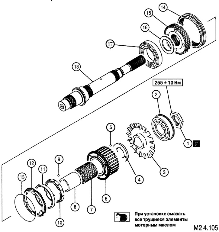
Disassembly sequence: 1. Locknut; 2. Ball bearing; 3. Oil guide impeller; 4. Adjusting washer of the position of the drive toothed pulley of the chain drive; 5. Steel ball; 6. Leading toothed pulley of chain transmission; 7. Needle bearing; 8. Needle bearing inner sleeve; 9. Steel ball; 10. The internal blocking ring of the synchronizer of the coupling of inclusion of the forward drive; 11. Two-conical ring; 12. External blocking ring of the synchronizer; 13. Synchronizer spring; 14. Movable ring of the front drive clutch; 15. Clutch hub; 16. Thrust washer; 17. Ball bearing; 18. Rear axle drive output shaft
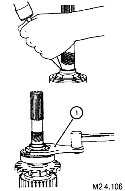
Removal and installation of the locknut of the output shaft of the rear axle drive of the transfer case Easy select
The lock nut is fixed by local indentation of the collar of the nut into the corresponding hollows of the shaft. Installation tightening torque: 255±10 Nm.

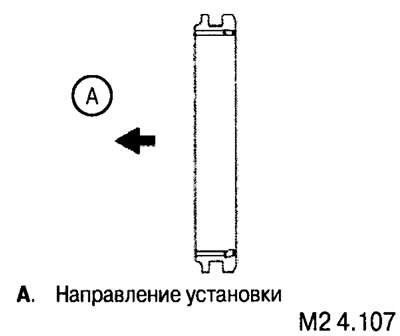
Installation of a movable ring of the coupling of inclusion of the forward drive
Figure M2 4.107 shows the correct position of the movable clutch ring.

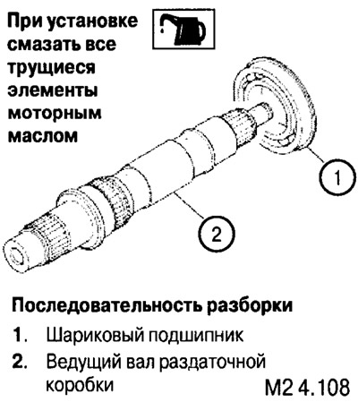
Disassembly and assembly of the drive shaft of the distribution box

