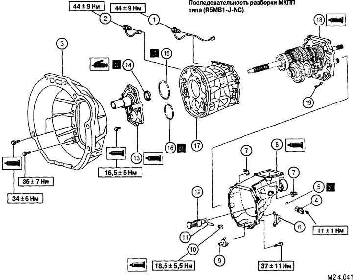
The sequence of disassembly of the manual transmission type (R5MB1-J-NC) (see fig. M2 4.041 - M2 4.043): 1. The switch of lanterns of a backing. 2. Limit switch for determining the position of the gear shift mechanism. 3. Clutch housing. 4. Vehicle speed sensor. 5. O-ring. 6. An arm of fastening of a plait of electroconducting. 7. An arm of fastening of a plait of electroconducting. 8. The back of the manual transmission case. 9. Oil sump tube. 10. Screw plug of the ball detent. 11. Split spring pin. 12. Pin of blocking of inclusion of transfer of a backing assy. 13. Front bearing housing. 14. Seal. 15. Retaining ring. 16. Retaining ring. 17. The middle part of the manual transmission case. 18. Intermediate plate (rear bearing housing). 19. Magnet. 20. Screw plug of the ball detent. 21. Spring of a lock of position of a rod of a gear change. 22. A ball of a fixer of provision of a rod of a gear change. 23. A lock ring of a rod of a gear change. 24. Stem shift fork No. 2. 25. Gearshift fork #2. 26. Roller-clamp of the mechanism for blocking the simultaneous engagement of gears. 27. A lock ring of a rod of a gear change. 28. Rod fork shift Ns1. 29. The pusher of the mechanism for blocking the simultaneous engagement of gears. 30. Roller lock mechanism, blocking the simultaneous engagement of gears. 31. Gearshift fork No. 1. 32. A lock ring of a rod of a gear change. 33. Split spring pin. 34. Stem shift fork No. 3. 35. Gearshift fork No. 3. 36. Roller-clamp of the mechanism for blocking the simultaneous engagement of gears. 37. Shaft lock ball #3. 38. A lock ring of a rod of a gear change. 39. Stem shift fork No. 4. 40. Ball position lock for the shift fork rod No. 4. 41. Spring. 42. E-ring. 43. Lever for reverse gear. 44. Fork reverse gear. 45. A lock ring of the bearing of a secondary shaft. 46. Roller bearing of the secondary shaft. 47. Ball. 48. Intermediate shaft bearing circlip. 49. Movable ring of the gear shift clutch No. 3. 50. Splined part of the 5th gear engagement gear. 51. External blocking ring of the synchronizer of 5th transfer.
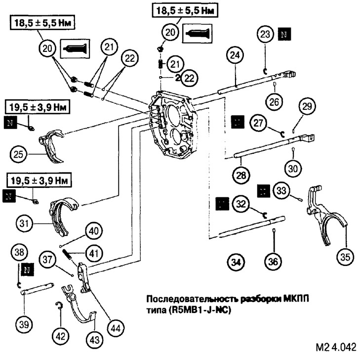
The sequence of disassembly of the manual transmission type (R5MB1-J-MC): 52. Drive gear 5th gear. 53. Retaining ring of the intermediate shaft. 54. Spring. 55. Spring. 56. Crackers synchronizer. 57. Needle bearing. 58. Thrust washer synchronizer 5th gear. 59. Pin. 60. The holder of the rear bearing of the intermediate shaft. 61. Retaining ring. 62. Parasitic reverse gear. 63. Roller cylindrical bearing. 64. Block of gears of an intermediate shaft. 65. Primary shaft assembly. 66. Secondary shaft assembly. 67. Arm of the lever of inclusion of transfer of a backing. 68. Intermediate plate with rear shaft bearing holders.
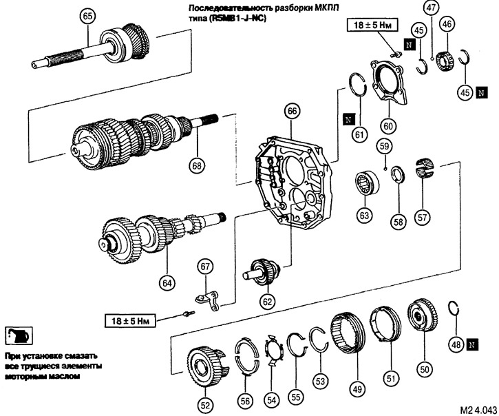
The sequence of disassembly of the manual transmission type (R5MB1-J-MC)
Assembly is carried out in the reverse order of disassembly.
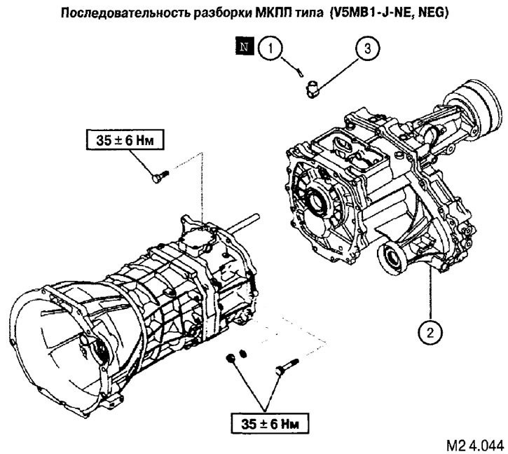
The sequence of disassembly of the manual transmission type (V5MB1-J-NE, NEG) (see fig. M2 4.044-M2 4.047): 1. Spring pin. 2. Transfer case. 3. Tip. 4. The switch of lanterns of a backing. 5. Limit switch for determining the position of the gear shift mechanism. 6. Clutch housing. 7 Reverse gear lock pin assembly. 8. Cover. 9. An arm of fastening of a plait of electroconducting. 10. An arm of fastening of a plait of electroconducting. 11. The back of the manual transmission housing. 12. Oil sump tube. 13. Screw cap ball detent. 14. Split spring pin. 15. Pin of blocking of inclusion of transfer of a backing assy. 16. An arm of fastening of a plait of electroconducting. 17. Front bearing housing. 18. Seal. 19. Retaining ring. 20. Retaining ring. 21. The middle part of the manual transmission case. 22. Intermediate plate. 23. Magnet. 24. Shaft-rod control gear shift. 25. Gear lever housing. 26. Screw plug of the ball retainer. 27. Spring for the position of the gearshift rod. 28. A ball of a fixer of provision of a rod of a gear change. 29. A lock ring of a rod of a gear change. 30. Shift fork stem #2. 31. Gear shift fork #2. 32. Roller-clamp A of the mechanism for blocking the simultaneous engagement of gears. 33. Retaining ring gearshift rod. 34. The shaft of the shift fork No. 1. 35. The pusher of the mechanism for blocking the simultaneous engagement of gears. 36. Roller-clamp of the mechanism for blocking the simultaneous engagement of gears. 37. Gearshift fork No. 1. 38. A lock ring of a rod of a gear change. 39. Split spring pin. 40. Stem shift fork No. 3. 41. Gearshift fork No. 3. 42. Roller-clamp of the mechanism for blocking the simultaneous engagement of gears. 43. A ball of a fixer of provision of a rod of a gear change. 44. A lock ring of a rod of a gear change. 45. The shaft of the shift fork No. 4. 46. A ball of a fixer of provision of a rod of a gear change. 47. Spring for the position of the gearshift rod. 48. E-ring. 49. Fork reverse gear. 50. Fork of inclusion of transfer of a backing. 51. Retaining ring bearing intermediate shaft. 52. Movable ring of the gear shift clutch No. 3. 53. Splined part of the 5th gear engagement gear. 54. External locking ring synchronizer 5th gear. 55. Drive gear 5th gear 5. 56. Retaining ring. 57. Spring. 58. Spring. 59. Crackers synchronizer. 60. Needle bearing. 61. Thrust washer synchronizer 5th gear. 62. Pin. 63. The holder of the rear bearing of the intermediate shaft. 64. Retaining ring. 65. Parasitic reverse gear. 66. Roller cylindrical bearing. 67. Block of gears of an intermediate shaft. 68. Primary shaft assembly. 69. Secondary shaft assembly. 70. Arm of the lever of inclusion of transfer of a backing. 71. Intermediate plate with rear shaft bearing holders.
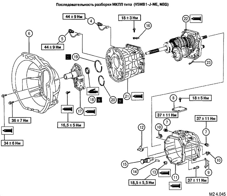
The sequence of disassembly of the manual transmission type (V5MB1-J-NE, NEG)
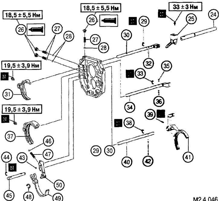
The sequence of disassembly of the manual transmission type (V5MB1-J-NE, NEG)
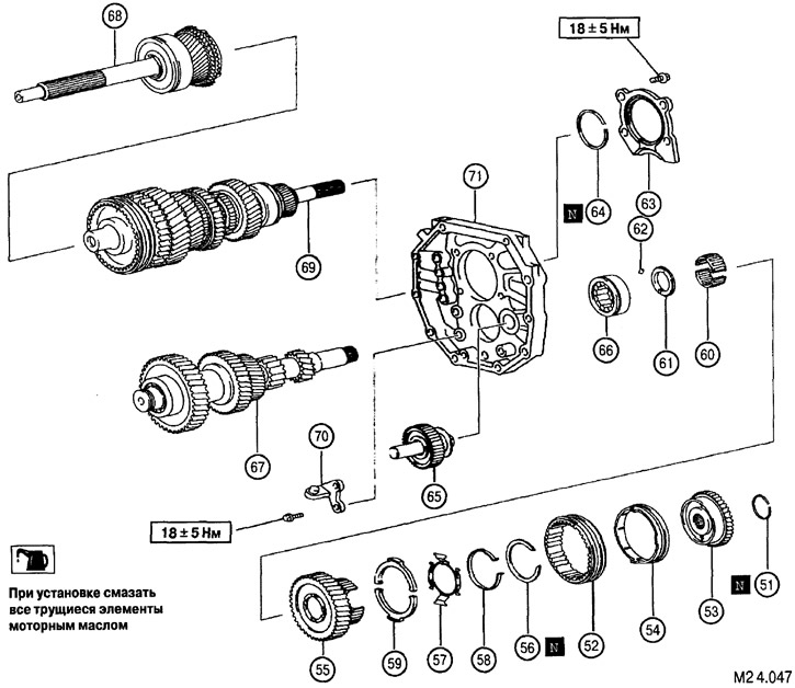
The sequence of disassembly of the manual transmission type (V5MB1-J-NE, NEG)
Assembly is carried out in the reverse order of disassembly.
