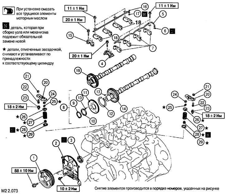
Note: an asterisk marks the parts removed and installed when replacing valve stem seals (28). In this case, when removing the valve crackers, it is necessary to set the piston of the corresponding cylinder to the TDC position.

1. Camshaft drive pulley; 2. Rear protective cover for timing belts; 3. Intake camshaft seal; 4. Front cover of the intake camshaft bearing; 5. Oil line lubrication x bearings; 6. O-ring; 7. Bearing caps; 8. Inlet camshaft assembly; 9. Snap ring; 10. Wavy elastic washer; 11. Additional gear; 12. C-spring; 13. Thrust pin; 14. Inlet camshaft; 15. Front cover of the exhaust camshaft bearing; 16. Oil line for bearing lubrication; 17. O-ring; 18. Bearing caps; 19. Exhaust camshaft assembly; 20. Push lever (rocker) assembled; 21. Locknut; 22. Adjusting screw; 23. Support hinge screw; 24. Valve stem cap; 25. Valve crackers; 26. Valve spring plate; 27. Valve spring; 28. Oil scraper cap; 29. Valve spring seat
Note: Parts marked with an asterisk are removed and installed as belonging to the corresponding cylinder.
Removal and installation of a gear drive pulley
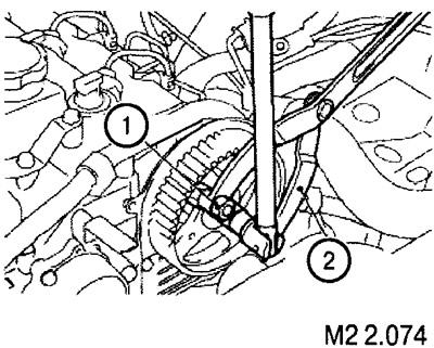
1. Screw the mounting studs into the pulley (1) and place a holder on them (2) (see fig. M2 2.074).

2. While holding the camshaft from turning, unscrew the fastening screw and remove the pulley from the shaft.
3. When installing the pulley later (holding the shaft) tighten the fastening screw with a torque of 88±10 Nm.
Removing bearing caps
1. Remove the oil lines with seals.
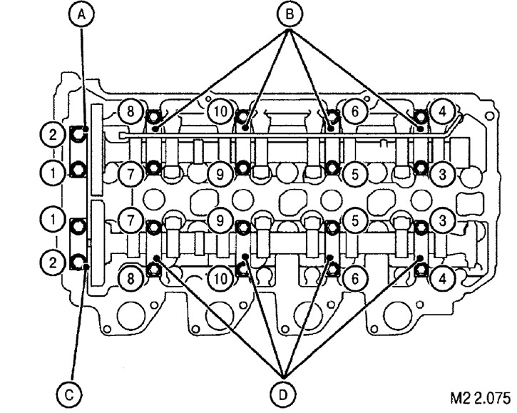
2. Loosen the screws securing the covers in pairs in accordance with the numbering in Figure M2 2.075, then unscrew the screws and remove the covers.

A. Front bearing cap, exhaust camshaft
B. Exhaust camshaft bearing caps
C. Intake camshaft front bearing cap
D. Intake camshaft bearing caps
