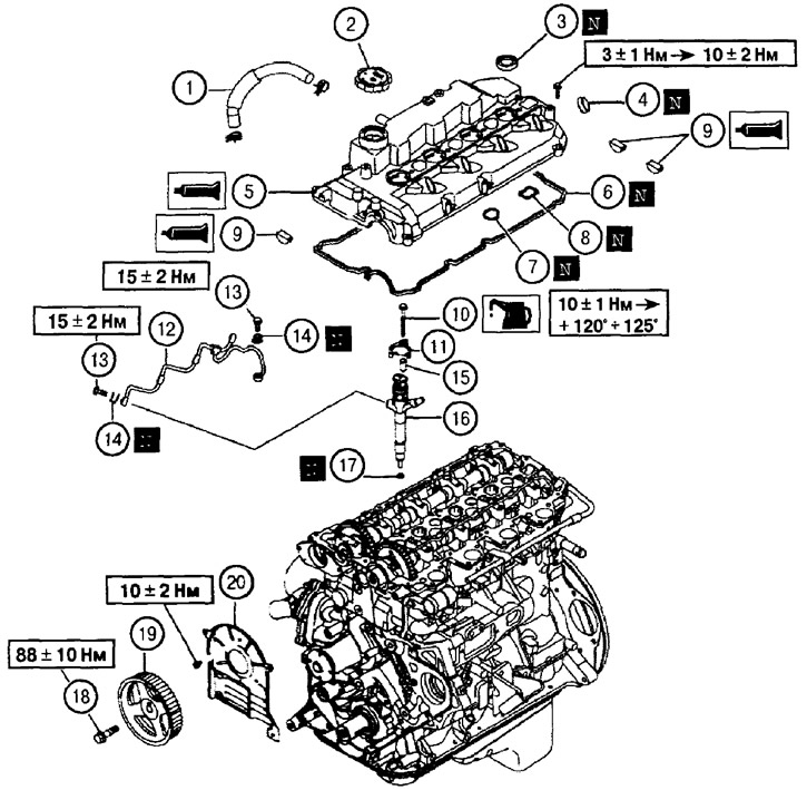
1. Branch pipe of the oil separation system; 2. Filler cap; 3. Oil seal of the nozzle body; 4. Oil inlet fuel pipe; 5. Valve cover; 6. Gasket «A»; 7. Gasket «IN»; 8. Gasket *C»; 9. Semicircular plug; 10. Screw for fastening the fuel injector body; 11. Fuel injector body holder; 12. Fuel return pipe; 13. Banjo bolt (hollow screw); 14. Gasket; 15. Holder post; 16. Fuel injector body; 17. Nozzle seal; 18. Screw for fastening the camshaft gear; 19. Camshaft gear; 20. Rear timing belt protection cover
* Removal of elements is carried out in the order of the numbers indicated in the figure
Removal and installation of a gear wheel of a camshaft
Holding the camshaft by the hex with a wrench, unscrew the mounting screw and remove the gear.
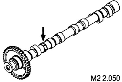
When installing, tighten the fastening screw with a torque of 88±10 Nm.
Installing fuel injector housings
1. Apply a small amount of oil to the threads of the mounting screws.
2. Install the nozzle bodies, racks and holders and tighten, without tightening, the fastening screws.
3. Install the fuel return pipe, new gaskets and tighten the banjo bolts to 15±2 Nm.
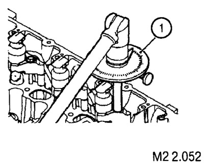
4. Tighten the screws securing the injector bodies to a torque of 10±1 Nm.
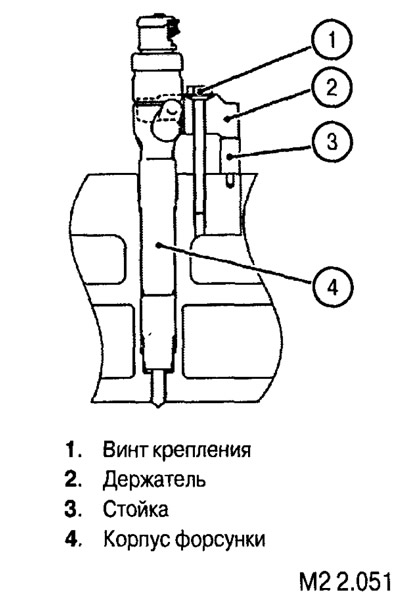
5. After tightening to the specified torque, finally tighten the fixing screws to an angle of 120°+125°.
Valve cover installation
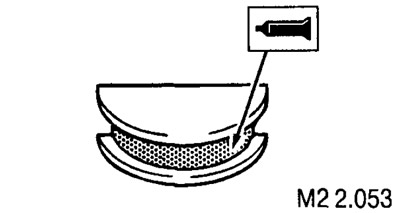
1. Apply a small amount of 3M ATD Part No. 8660 sealant or equivalent to the plug and install the plug in place in the cylinder head (see fig. M2 2.053).
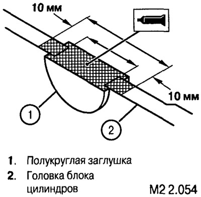
2. Apply a small amount of 3M ATD Part No. 8660 sealant or equivalent to the surface of the plug and cylinder head as shown (see fig. M2 2.054).
3. Install gasket, valve cover and mounting screws.
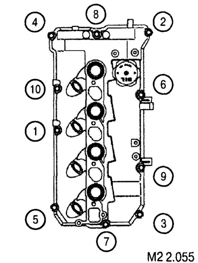
4. Tighten the screws with a torque of 3.0±1.0 Nm in the order shown in the figure.
5. Re-tighten all screws to 10±2 Nm in the same order.
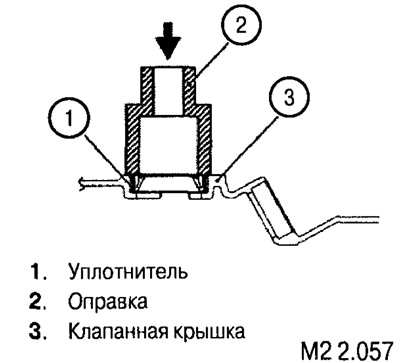
Installing oil seals in the valve cover
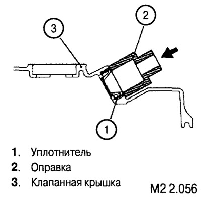
New seals are installed using suitable mandrels (e.g. socket head), as shown in the pictures.
 |  |
