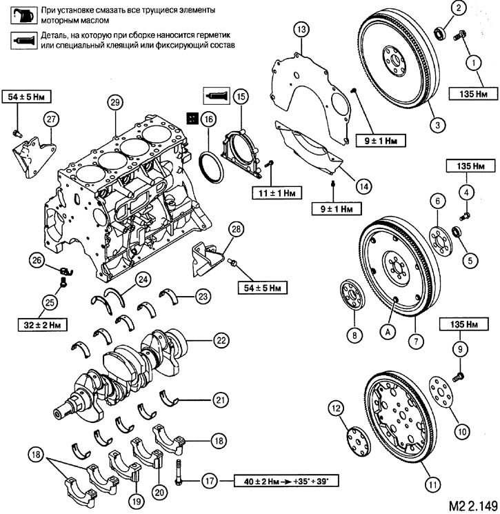
1. Flywheel screw (manual transmission-2WD); 2. Ball bearing (manual transmission-2WD); 3. Flywheel (MKnn-2WD); 4. Flywheel screw (Manual-4WD); 5. Ball bearing (Manual-4WD); 6. Adapter plate (MKnn-4WD); 7. Elastic flywheel (Manual-4WD); 8. Crankshaft adapter plate (Manual-4WD); 9. Adapter plate fixing screw (automatic transmission); 10. Adapter plate (automatic transmission); 11. Torque converter mounting plate (automatic transmission); 12. Crankshaft adapter plate (automatic transmission); 13. Rear plate; 14. Flywheel housing cover; 15. Flywheel rear oil seal housing; 16. Rear flywheel oil seal; 17. Screws of fastening of covers of radical bearings; 18. Caps of main bearings No. 1, 2 and 5; 19. Main bearing cap No. 3; 20. No. 4 main bearing cap; 21. Lower root bearings; 22. Crankshaft; 23. Top root bearings; 24. Thrust bushings (bearings for axial run-up of the shaft); 25. Nozzle bypass valve; 26. Oil nozzles; 27. Engine support bracket, right; 28. Engine support bracket, left; 29. Cylinder block
Removal of elements is carried out in the order of the numbers indicated in the figure
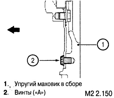
Attention: if the engine is equipped with a flexible flywheel, do not unscrew the screws (A), as this can lead to an imbalance of this flywheel.
Removal and installation of a flywheel (manual transmission) or adapter plate (automatic transmission)
Unscrewing and tightening the screws securing the flywheel or adapter plate must be done by fixing the flywheel with a lock (1).
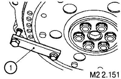
When installing the flywheel, tighten the fastening screws with a torque of 135±5 Nm.
Removal and installation of oil nozzles
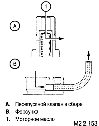
There are two types of injectors installed in the block (left and right). When installing, make sure they are properly installed.
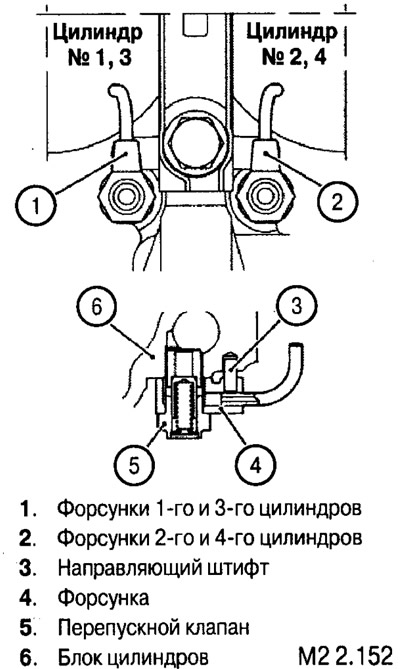
After removing or before installing the injectors, check the cleanliness of the injector passages and the bypass valve.
Checking the block of cylinders
After removing all parts from the block, clean its surfaces and blow out all channels with compressed air.
Non-flatness test
Using a measuring ruler and a set of flat feeler gauges, check the gaps between the ruler and the plane of the block in the directions shown in the figure.
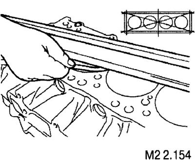
The standard gap value is 0.05 mm.
The maximum allowable value is 0.1 mm.
If the flatness exceeds the maximum allowable value, the block must be replaced.
Cylinder check
Visually inspect the cylinder walls for scratches and burrs.
Using a bore gauge, measure the diameters of each cylinder in the directions shown in the figure. Based on the measurement results, determine the arithmetic mean of the diameter for each cylinder.
Determine also the ellipse of the cylinder (as the difference between the measurement of diameters in points «A» And «IN» in every section).
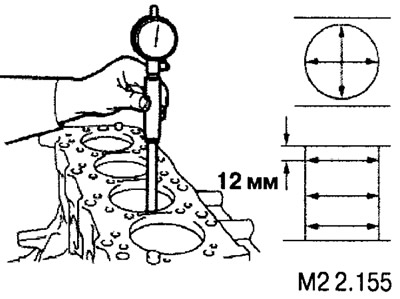
The standard value for the cylinder diameter is 91.01-91.13.
Ellipsity - 0.02 mm.
If the measured values exceed the permissible values, it is necessary to bore and honing the cylinders to the repair size, respectively, with the replacement of pistons and piston rings.
The piston size is determined by the largest cylinder diameter measured.
Note: Pistons are supplied as spare parts in two repair sizes (+0.50 mm) And (+1.00 mm). Dimensional marking is applied on the piston crown (0.50 or 1.00).
The size of the cylinder diameter for boring is determined based on the measurement of the diameter of the repair piston + 0.02 mm.
Note: All four cylinders must be bored.
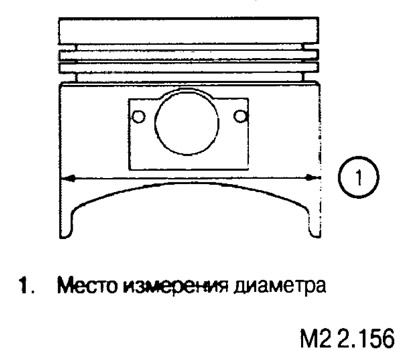
After finishing the cylinders, check the clearance between the piston and the cylinder bore (calculated as the difference between the measurements of the cylinder diameter and the new piston).
The gap should be within 0.03-0.05 mm.
Crankshaft and bushings
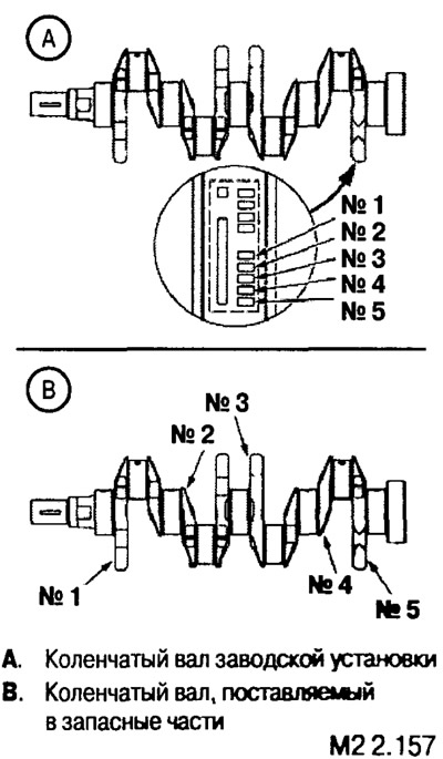
Crankshaft marking.
Factory installed crankshafts and those supplied as spare parts are marked differently.
The marking includes data on the diameter of the main journals of the shaft.
The factory installed crankshaft journal diameters are marked as shown.
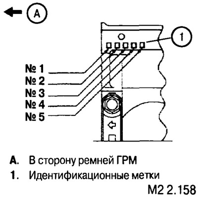
Dimensional groups of diameters of holes of beds of main bearings are stamped on the block of cylinders.
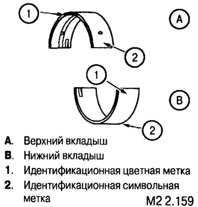
The size group of the main bearing shells is marked with a symbolic or color mark.
Note: the upper liners installed in the bed of the block have grooves and holes for lubrication; the lower liners installed in the covers do not have holes and grooves.
Note: The data given in the table should be used only when selecting liners for replacement or when replacing the crankshaft.
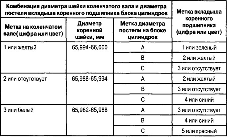
Note: if the crankshaft has been reground, it is necessary to select bearings of repair dimensions. There are no data on repair size inserts in the database.
Installing the crankshaft, main bearing caps, tightening the fastening screws and checking the axial run-up of the crankshaft
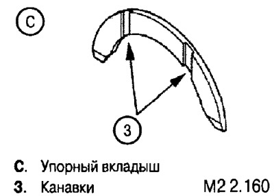
Install thrust bearings and upper main bearings (grooved) in the bed of the block, and the bottom (without grooves) - into the caps and lubricate with a thin layer of engine oil.
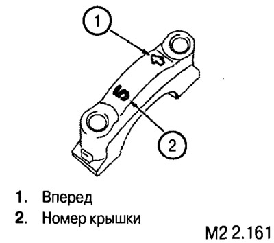
Install crankshaft, install covers (according to the markings on them) and fasten the fixing screws.
Tighten the fixing screws to 40±2 Nm.
Note: Combination bushings can be installed on the middle shaft support (with a side that acts as a thrust insert). In this case, thrust bearings (24) (see fig. M2 2.149) are not installed. The top and bottom bushings are identical in design, have a hole, but do not have an oil groove.
When selecting inserts, it is necessary to be guided by the data given in the table.
After torque tightening, tighten the screws to an angle of 35-39°.
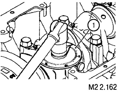
Note: final tightening to an angle less than or greater than the specified values is not allowed. If for some reason the angle turned out to be less or more than the recommended values, it is necessary to completely loosen the screws and repeat the tightening again.
After tightening the bearing cap screws, check that the crankshaft turns smoothly without binding and check the axial movement (takeoff run) shaft.
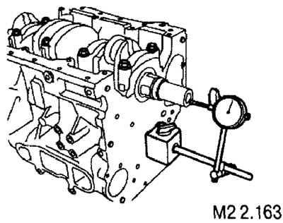
Standard value: 0.05-0.25 mm.
Maximum allowable value: 0.45 mm.
If the measured value is higher than the maximum allowable value, the thrust bearings must be replaced.
Determining bearing clearance using a plastic gauge
1. Remove oil from the bearing surface and crankshaft journal.
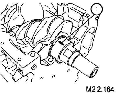
2. Cut off a piece of plastic gauge (1), the length of which corresponds to the width of the liner, and place it on the shaft neck along the rest.
3. Install the cover and tighten the screws as described above.
4. Unscrew the screws, remove the cover and measure the width of the crumpled gauge at the widest part (using the scale supplied with the gauge).
The gap value obtained on the scale must be within acceptable limits.
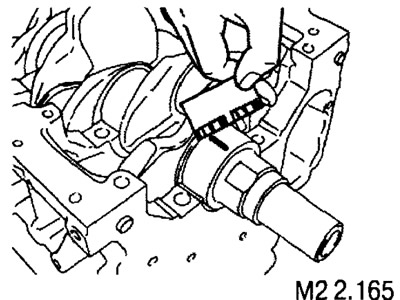
Nominal gap value: 0.040-0.055 mm.
Maximum allowable clearance: 0.10 mm.
