In subsection «Wiring diagrams» wiring diagrams of intermediate connectors are given (J/C), indicating the connected systems and communication signals. Drawings are provided showing the placement of relays, fuses and fuses in blocks located in the engine compartment and cabin (J/B), consumer switching circuits and diagrams of all vehicle systems, indicating power sources, current flow and signal exchange. The appearance and numbering of the contacts of the corresponding connectors of the main elements of this system is given, the color marking of the connecting wires, etc. is shown. In order to exclude differences in the interpretation of certain terms and elements, the original (English) titles.
Note: in each case, when considering a particular scheme, it is necessary to take into account the equipment of a particular car (the presence or absence of a particular system or equipment).
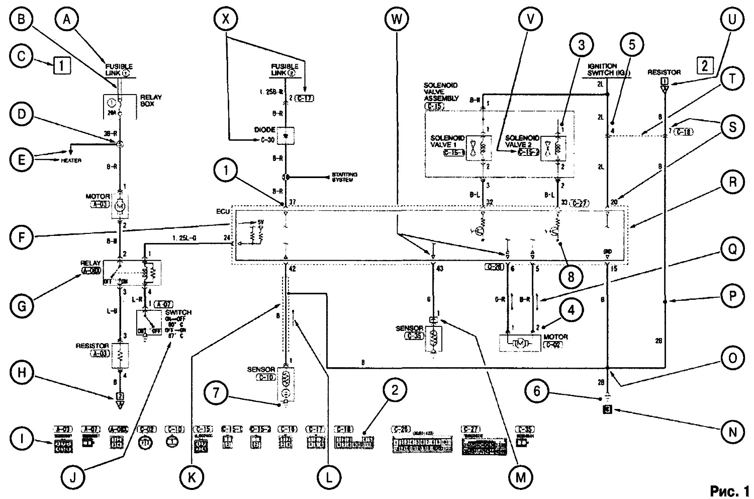
Each circuit diagram shown in the figure is an image of a separate system or subsystem that is part of the vehicle's electrical equipment.
The upper part of the diagram shows the source of supply voltage «+», at the bottom - connection points on «mass».
Открыть большую картинку в новой вкладке »
| Designation in fig. 1 | Explanation to the scheme | |
| A | Voltage supply (in the bottom case - fusible insert No. 1). | |
| IN | Shown is the connection between fuse #1 and fuse #1 in the relay and fuse box. | |
| WITH | Each circuit diagram is presented as one or more blocks (in this case two blocks 1 and 2). | |
| D | Designation for the wire connection point number of another system that is connected to the system in question. | |
| E | The name of the system or element associated with the system in question. | |
| F | Indicates the value of the supply voltage (in this case in the control unit). If the voltage value is not specified, then it is considered equal to the voltage in the on-board network. | |
| G | Designation"X" after the connector number indicates that the corresponding relay is connected to this connector. | |
| H | Arrow and number (in this case, 2) indicates that this chain continues on the second block of the scheme of this system. | |
| 1 | Shows connector configuration and pin numbering. | |
| J | Operating parameters indicated (in this case, the on / off temperature of the coolant temperature sensor). | |
| TO | Shielding braided wire. | . |
| L | The arrow indicates the direction of the current. | |
| M | Indicates that this connector is (in this case the sensor connector) does not receive voltage. | |
| N | Attachment point number designation on «mass» (in accordance with the drawings in the layout diagrams of electronic and electrical components and connection points on «mass» car). | |
| ABOUT | The connection point of the wires is marked. | |
| R | Shows the point at which the section or color of the given wire changes. | |
| Q | A double arrow means that current in a given conductor can flow in different directions. | |
| R | broken line (---) indicates that the pins belong to the same connected connector. | |
| S | The pin number of the corresponding connector. | |
| T | broken line (---) indicates that the pins belong to the same intermediate connector. | |
| And | Arrow and number (in this case, 1) indicates that this circuit starts on the first block of the circuit of this system. | |
| V | Indicates the connector number and pin number in that connector (in accordance with the drawings in the layout diagrams of electronic and electrical components and connection points on «mass» car). | |
| W | Indicates the direction of the input or output signal in the electronic control unit. | |
| X | Connector number designation in the wiring harness (in accordance with the drawings in the layout diagrams of electronic and electrical components and connection points on «mass» car). If the connector number is not surrounded by a box, this means that the corresponding device is included in the wire break (in this case, a diode). |
Connectors and connection points on «mass»
Connector markings
Connectors are marked with an alphanumeric coding, in which the letter determines the location of the connector in one or another part of the car, in accordance with the data given in the table.
| Letter designation | Connector location | Letter designation | Connector location |
| A | Engine compartment | D | Floor and roof |
| IN | Transmission | E | doors |
| WITH | Dashboard | F | Frame |
Designation of connectors and connection points on «mass» (see fig. 1)
1. Type and designation of connectors and contacts.

2. View of the connector and pin numbering.

Designation of connectors depending on the type of connected element
3. The harness connector is connected directly to the item or device.

4. The harness connector is connected to an item or device that has a connector harness.

5. Intermediate harness connectors.

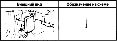
Connection points with «weight»
6. Wire or cable connection.
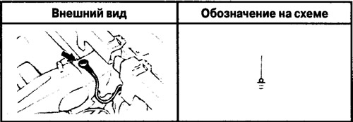
7. Element connection (sensor).
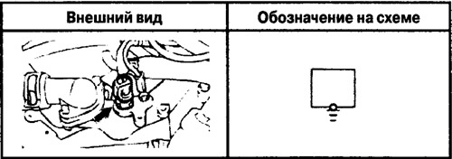
8. Connection of the electronic unit (ECU).
Wire marking
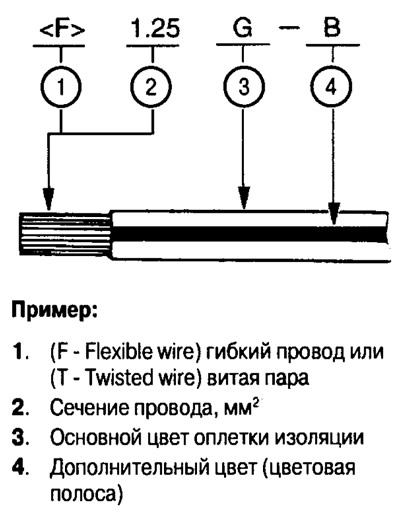
Wire sheath color designation
| IN | (Black) | Black |
| L | (Blue) | Blue |
| PU | (Purple) | Purple |
| V | (Violet) | Violet |
| BR | (Brown) | Brown |
| LG | (Light green) | light green |
| R | (Red) | Red |
| W | (White) | White |
| G | (Green) | Green |
| ABOUT | (Orange) | Orange |
| SB | (Sky blue) | Blue |
| Y | (Yellow) | Yellow |
| GR | (Grey) | Grey |
| R | (Pink) | Pink |
| SI | (Silver) | Silver |
