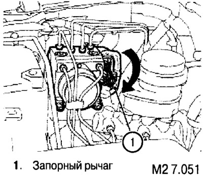
2. Turn the locking lever of the ABS-ECU connectors down and disconnect the A-01 connector.
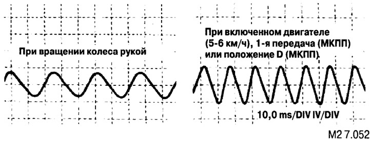
3. Connect a voltmeter or oscilloscope to the connector (not to the ABS-ECU) and, rotating the wheels by hand at a speed of 0.5-1 revolution per second, measure the outgoing voltage. It should be:
- 42 mV or higher when using a multimeter;
- 120 mVp-p or higher when using an oscilloscope.
If the voltage is less, check the gap between the sensor and the rotor. If the clearance is correct, replace the sensor.
Using an oscilloscope, based on the waveform, you can draw conclusions about the condition of the sensor and other elements of the ABS system. To do this, turn on the engine, turn on the first gear (manual transmission) or move the selector lever to position D (automatic transmission). It is also allowed to take data from the oscilloscope while driving. In this case, the output voltage should increase with faster travel and decrease with slower travel.
 |  |
| Waveform | Probable Cause | Solution |
| Too small amplitude | Faulty speed sensor | Replace sensor |
| Excessive fluctuations in amplitude (if the smallest amplitude does not exceed YuOmV) | Worn or worn hub axle | Replace hub |
| Faulty ABS-ECU ground | Repair wiring | |
| uneven waveform | Open circuit in speed sensor | Replace sensor |
| Open circuit in wiring | fix the wiring | |
| Incorrectly installed wheel speed sensor | Reinstall correctly | |
| Damaged rotor tooth | Replace ABS Rotor |

Note: Since the wheel speed sensor wires move with the front or rear suspension, there is a possibility that the circuit may only open when driving on rough roads; therefore, it is recommended to check the output voltage of the sensor in rough road conditions.
In case of battery discharge
If, in the case of a discharged battery, the engine is jump-started and driven without waiting for the battery to recharge, the engine may misfire and stop. This happens because the ABS system requires a lot of energy for self-diagnosis when turned on. To solve this problem, fully recharge the battery.
