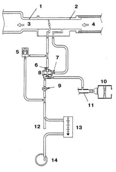
Check of serviceability of functioning of a control system of a purge of an adsorber on models 2.4 l
1 - Discharge chamber of the inlet pipeline; 2 - Throttle body; 3 - To the combustion chambers; 4 - From the air cleaner; 5 - Purge control solenoid valve (normally locked); 6 - Fitting A; 7 - Fitting B; 8 - Purge control valve; 9 - Control valve; 10 - Air cleaner; 11 - Air duct; 12 - Purge hose; 13 - Flow meter (MV991700); 14 - Carbon adsorber
General information
Changes in atmospheric pressure and ambient temperature lead to differences in relative pressure inside the fuel tank. If the tank had a non-hermetic design, then under excess pressure, the air inside, stuffed with fuel vapors, would come out.
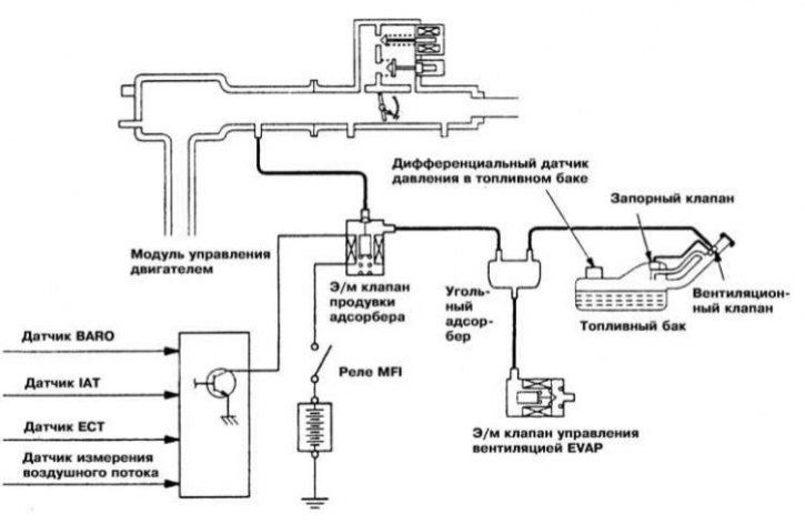
The EVAP system accumulates fuel vapors accumulated in the sealed tract of the power system during parking and ensures that they are removed to the intake tract for combustion during normal engine operation. The improvement of the system is carried out continuously as the requirements for environmental protection become more stringent.
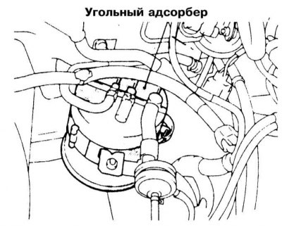
As a receiver that accumulates fuel vapors, a sealed container filled with activated carbon granules is used - a carbon adsorber. At the top of the adsorber there is a ventilation cover that allows the container to be purged with fresh air. The fuel vapors removed from the canister during purge enter the intake manifold and burn out during the normal operation of the engine.
Special control valve (purge valve) provides purge of an adsorber for a certain time under the corresponding operating conditions of the engine. The valve has a normally closed design (closed when power is off), operates under the control of the PCM and, when the ground circuit is opened, provides a vacuum to the adsorber.
During engine warm-up and for some time after a hot start, the PCM keeps the valve ground loop closed. The adsorber is purged only when the temperature of the coolant reaches a value of about 49°C. While the engine is idling, the PCM may intermittently close the valve to make adjustments to the air/fuel mixture.
For safety reasons, the fuel tank filler cap is equipped with a two-way safety valve through which, if necessary, the internal pressure in the tank is equalized with atmospheric pressure.
On those equipped with a second-generation on-board diagnostic system (OBD-II) EVAP system failures are logged as codes in processor memory. Monitoring is carried out by means of a differential pressure sensor mounted in the fuel tank and a purge intensity sensor that monitors the flow rate of the gas flow output from the adsorber to the engine. The description of principles of functioning of systems OBD and the list of codes of malfunctions are given below in this Chapter.
Examination
Note. A complete diagnosis of the EVAP system is one of the procedures that is beyond the skill of the average amateur mechanic and should be entrusted to a car service specialist. Note that system components are subject to additional federal warranties. Most often, EVAP system failures are due to damage to the carbon canister or connecting lines.
1. Violation of the stability of the idle speed, a decrease in the efficiency of the engine's return, spontaneous shutdowns of the latter can be caused by a failure of the control valve, damage to the carbon adsorber or connecting hoses of the EVAP system, as well as improper laying of the latter. Also check the condition of the fuel filler cap.
2. Obvious loss of fuel, as well as the appearance of a strong smell of the latter during parking, can be caused by leaks in the gas lines, or damage to the carbon canister body, malfunction of the control valve, disconnection, or violation of the patency of the evaporator lines, as well as improper laying of the latter.
3. Check the condition, route, and connection of all EVAP system hoses. Make any necessary repairs or replacements. Damaged components.
4. Inspect the bottom of the adsorber for signs of leaks, replace if necessary - make sure the hoses are connected correctly.
5. Check the patency of the filter and control valve. Blow out the adsorber with low-pressure air - air is supplied through the tube coming from the fuel tank and must freely exit through other tubes connected to the assembly. A defective adsorber must be replaced (see below).
Canister Purge Control System
Models 1990÷1993 ed., except those equipped with a 2.0 l DOHC turbocharged engine (1990÷1992)
1. Disconnect the vacuum hose marked with red stripes from the throttle body and connect a hand vacuum pump to it.
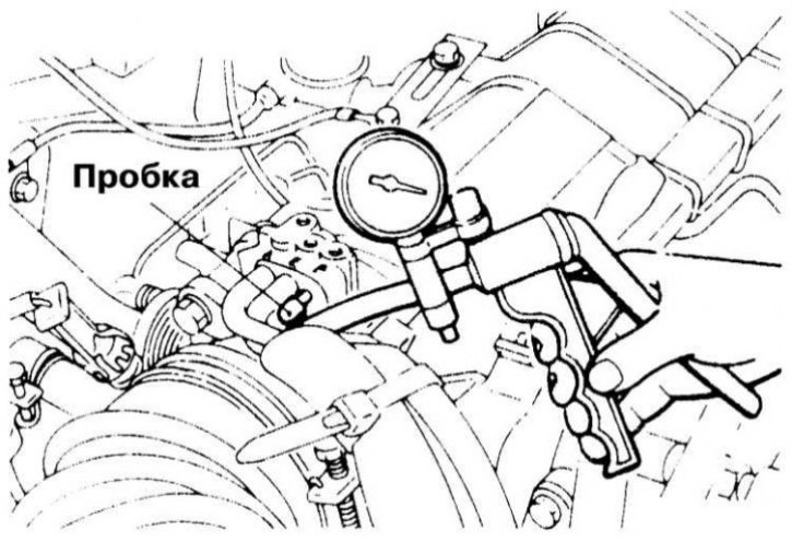
2. Seal the open fitting on the throttle body.
3. Wait for the coolant to cool down to a temperature below 60°C and, with the engine running at idle, create a vacuum on the valve with a depth of 376 mm Hg. Art., - it must be securely held by the valve assembly. The same picture should take place at idle and after warming up the engine above 70°C.
4. Now raise the engine speed to 3000 rpm and repeat the test until the 3 minute interval has elapsed - vacuum should not be created. When the engine is running at high speed for more than 3 minutes, the possibility of creating a vacuum should be restored in the absence of the fact of its retention.
Note. If the test is carried out at an altitude of more than 2200 m above sea level, or at an intake air temperature of more than 50°C, vacuum leakage will occur constantly.
5. At negative results of the check described above it is necessary to make replacement of the operating valve.
Models 1990÷1992 ed., equipped with a 2.0 L DOHC turbocharged engine
1. Disconnect the purge hose from the intake duct and plug it.
2. Connect a hand vacuum pump to the hose.
3. Wait for the coolant to cool down to a temperature below 60°C and, with the engine running at idle, create a vacuum on the valve with a depth of 376 mm Hg. Art., - it must be securely held by the valve assembly. With an increase in speed to 3000 per minute, the tightness of the valve should also not be violated.
4. Now warm up the engine to a coolant temperature above 70°C and repeat the check: at idle, the vacuum must again be reliably held by the valve, at an engine speed of 3000 rpm during the first 3 minutes it is possible to create the required pressure on the valve (376 mmHg Art.) rarefaction should be absent, then it should be created instantly in the absence of the fact of its retention.
Note. If the test is carried out at an altitude of more than 2200 m above sea level, or at an intake air temperature of more than 50°C, vacuum leakage will occur constantly.
5. At negative results of the check described above it is necessary to make replacement of the operating valve.
Models since 1994 issue.
1 Connect a type MB991700 flow meter between the purge hose and the charcoal adsorber.
2. Engage neutral (RKPP), or move the selector lever to the position "R" (AT). Turn off all onboard electrical consumers and warm up the engine to normal operating temperature (80÷95°C).
3. Let the engine idle for 3-4 minutes, then depress the foot brake pedal several times while reading the gauge. The required value is 20 cm/sec.
4. If the measurement result is below the specified value, repeat the test with the vacuum hose disconnected from the adsorber - if necessary, remove the reason for blocking the latter. If disconnecting the hose does not lead to the required increase in the intensity of the purge, check the patency of the fitting of its connection on the adsorber body, also try to replace the solenoid and executive valves for purge control.
5. If the purge rate is within specification, replace the charcoal canister.
Purge control valve
Models 1990÷1993 ed., equipped with a 2.0 liter turbocharged engine
1. Remove the charcoal canister purge control valve located to the right of the battery.
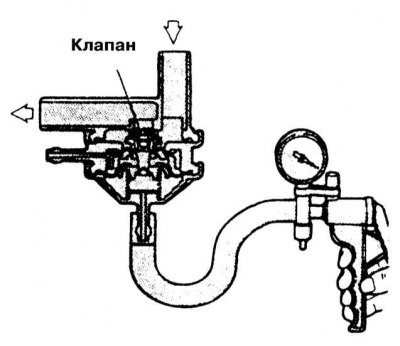
2. Connect a hand vacuum pump to the vacuum port on the valve.
3. Check the tightness of the valve assembly: the valve should begin to pass the air supplied to the connection to the adsorber only when a vacuum is created on it with a depth of about 203 mm Hg. st..
4. Now connect the pump to the pressure port of the valve and apply a vacuum of 399 mmHg. Art., - the valve must remain tight.
5. A defective valve must be replaced.
EVAP canister purge solenoid valve
Models 1990÷1993 ed., except those equipped with a 2.0 l DOHC turbocharged engine (1990÷1992)
1. Tag and disconnect the two vacuum hoses from the purge control solenoid valve.
2. Disconnect the electrical wiring from the valve.
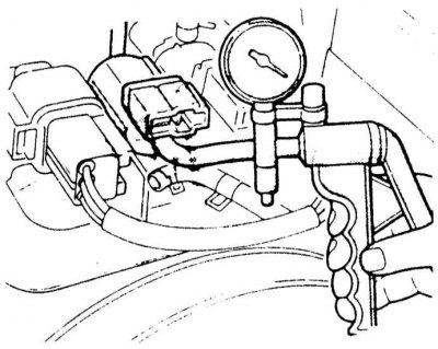
3. Connect a hand vacuum pump to the connection fitting marked with red stripes on the vacuum hose on the valve assembly.
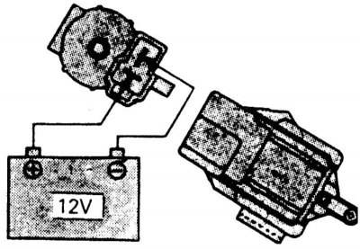
4. Create a vacuum on the valve and check the tightness of the assembly with and without battery voltage applied to it: in the first case, the vacuum should not be held, in the second it should.
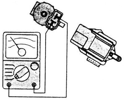
5. Measure the resistance between the valve connector terminals. The required value is 36÷44 Ohm at 20°C.
6. A defective valve must be replaced.
Models 1990÷1992 ed., equipped with a 2.0 L DOHC turbocharged engine
1. Tag and disconnect the two vacuum hoses from the purge control solenoid valve.
2. Disconnect the electrical wiring from the valve.
3. Connect a hand vacuum pump to the connection fitting marked with red stripes on the vacuum hose on the valve assembly.
4. Create a vacuum on the valve and check the tightness of the assembly with and without battery voltage applied to it: in the first case, the vacuum should be maintained, in the second - no.
5. Measure the resistance between the valve connector terminals. The required value is 36÷44 Ohm at 20°C.
6. A defective valve must be replaced.
Models since 1994 issue.
1. Tag and disconnect the vacuum hoses from the purge control solenoid valve.
2. Disconnect the electrical wiring from the valve.
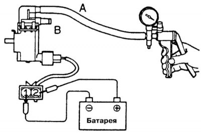
3. Connect a hand vacuum pump to port A on the valve assembly.
4. Create a vacuum on the valve and check the tightness of the assembly with and without battery voltage applied to it: in the first case, the vacuum should be maintained, in the second - no.
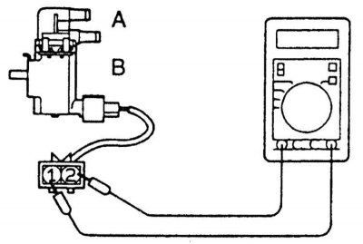
5. Measure the resistance between the valve connector terminals. The required value is 25÷44 Ohm at 20°C.
6. A defective valve must be replaced.
Removing and installing components
Carbon adsorber
1. Disconnect the negative cable from the battery.
Attention! If the stereo system installed in the car is equipped with a security code, before disconnecting the battery, make sure that you have the correct combination to activate the audio system!
2. If necessary, jack up the vehicle and place it on jack stands. Remove the right front wheel and the arch protection locker.
3. Having previously carefully marked, disconnect all vacuum lines from the adsorber.
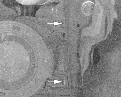
4. Turn out fixing bolts / release clamps and remove assemblage of an adsorber from the car.
5. Installation is carried out in the reverse order.
Solenoid valves
1. Disconnect the negative cable from the battery.
Attention! If the stereo system installed in the car is equipped with a security code, before disconnecting the battery, make sure that you have the correct combination to activate the audio system!
2. Carefully mark and disconnect vacuum hoses and electrical wiring from the canister purge control solenoid valve.
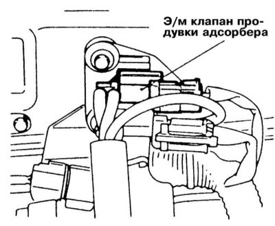 | 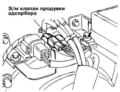 |
3. Remove the valve assembly with the support bracket and remove it from the vehicle's engine compartment.
4. Installation is carried out in the reverse order.
