Information about diagnostic tools
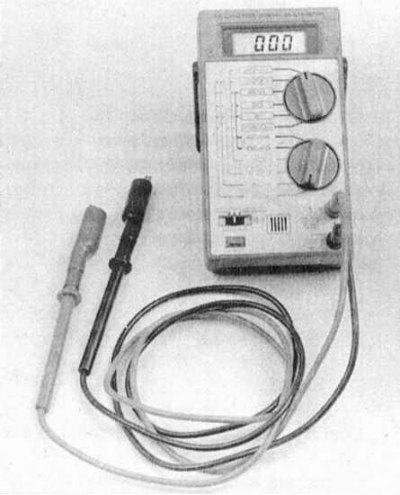
Checking the correct functioning of the components of the injection systems and reducing the toxicity of exhaust gases is carried out using a universal digital meter (multimeter). The use of a digital meter is preferred for several reasons. Firstly, it is quite difficult for analog devices to (sometimes impossible), determine the result of the indication with an accuracy of hundredths and thousandths, while when examining circuits that include electronic components, such accuracy is of particular importance. The second, no less important, reason is the fact that the internal circuit of a digital multimeter has a fairly high impedance (the internal resistance of the device is about 10 million ohms). Since the voltmeter is connected in parallel to the circuit under test, the measurement accuracy is the higher, the less parasitic current will pass through the device itself. This factor is not significant when measuring relatively high voltage values (9÷12 V), however, it becomes decisive in the diagnosis of elements that produce low-voltage signals, such as, for example, an oxygen sensor, where it is a matter of measuring fractions of a volt.
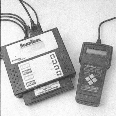
The most convenient devices for diagnosing engine control systems of modern car models are manual scanner-type readers. First generation scanners are used to read fault codes for OBD-I systems. Before use, the reader should be checked for compliance with the model and year of manufacture of the vehicle being checked. Some scanners are multifunctional, due to the possibility of changing the cartridge depending on the model of the car being diagnosed (Ford, GM, Chrysler, etc.), others are tied to the requirements of regional authorities and are intended for use in certain areas of the world (Europe, Asia, USA, etc.), see below for details.
With the introduction of a second-generation on-board diagnostic system that meets the latest environmental legislation (OBD-II) Readers of a special design began to be produced. Some manufacturers have launched scanners designed for use by amateur mechanics at home - ask in car accessories stores.
Note. Despite the fact that reading fault codes in OBD II systems is not possible without the use of a special scanner, some of the simplest checks of individual system components are described below in this Chapter.
Parallel monitoring of signal parameters, resistances and voltages in all control circuits is possible using a splitter connected in series to the engine control unit connector. At the same time, with the engine turned off, running or while the car is moving, the parameters of the signals at the splitter terminals are measured, from which a conclusion is made about possible defects.
Special diagnostic scanners are used to diagnose electronic systems of the engine, automatic transmission, ABS, SRS (Pointer) or testers (Retriever) with a specific cartridge (if provided), universal cable and connector. In addition, for this purpose, you can use an expensive specialized automotive diagnostic computer, specially designed for the complete diagnosis of most systems of modern cars (e.g. ADC2000 from Launch HiTech, or ESA 560, FSA, BEA from BOSH), or a conventional computer with a special cable and the OBD II browser program.
Some scanners, in addition to the usual diagnostic operations, allow, when connected to a personal computer, to print circuit diagrams of electrical equipment stored in the memory of the control unit (if laid down), program the anti-theft system, observe the signals in the car circuits in real time.
In principle, reading the fault codes stored in the memory of the self-diagnosis system on some vehicles can also be done using the failure warning lamp (MIL) /"Check engine" on the dashboard.
The scanner only reads the entered fault memory and clears the fault memory. In addition, the scanner only supports the ISO protocol. The tester can additionally activate and display current data and supports SAE and ISO protocols.
All tester cartridges can also be used in the scanner. In this case, the functions will be limited to only reading and clearing memory.
For diagnostics, for example, devices from ToolRama Inc. can be used. (3500 NW Boca Raton Blvd., Boca Raton, Florida, 33431, USA 1 877 866 5726 - 561 750 4511 - 561 338 8447 FAX):
- R000 tester or P000 scanner with T044 or T054 cartridges,
- Universal cable N000, Connector N04A;
- Multiplexer N002A.
With devices offered by the company "BOSCH", You can get acquainted on the website: bosch.de.
For most vehicles manufactured since 1996 that support the SAE/ISO 9141 OBD II protocol, an OBD II cartridge can be used that performs the following functions:
- Reading and clearing OBD II trouble codes. Displays oxygen sensor test results.
- Continuous monitoring of ignition, injection and component systems.
- Displaying a list of current data and fixed transient failures:
- a) Absolute pressure in the inlet pipeline;
- b) Oxygen sensor voltage;
- c) Engine coolant temperature;
- d) Estimated engine load;
- e) vehicle speed;
- f) fuel quality;
- g) Air flow (by weight);
- h) Ignition advance;
- i) Throttle position;
- j) Intake air temperature.
In addition to trouble codes "P0", the instrument also displays extended codes "P1" for models Acura, Audi, BMW, Chrysler, Dodge, FORD, Geo, GM, Honda, Hyundai, Infinity, Kia, Lexus, Lincoln, Mercury, Mazda, Mercedes, Mitsubishi, Nissan, Porsche, Saturn, Seat, Skoda, Subaru, Suzuki, Toyota, Volvo, VW.
Features of ADC2000 specialized automotive diagnostic tool:
- Built-in 4-channel oscilloscope with standard preset for 19 probes.
- Ignition analyzer for testing primary and secondary circuits (with voltage up to 100 kV) on systems with a distributor or separate ignition coils - with control of burning time, peak voltage, ignition timing, current, and revolutions.
- Two-channel multimeter with digital and graphical representation of voltage data (150V), frequency (1100 kHz), current (150A).
- Built-in scanner for the main systems on cars: VAG, MB, BMW, Volvo, Toyota / Lexus, Mitsubishi, Nissan, Honda, Mazda, GM, Ford, Chrysler, Daewoo, Hyundai, Kia, Samsung, as well as on cars that support the OBD protocol II.
- No cartridges required – you can update the instrument software yourself by downloading the necessary updates via the Internet.
- Software for communication with a personal computer.
Information on the use of these devices is contained in the enclosed documents. For more information about the instruments, visit programatools.com, bosh.de and lasn.com.
For diagnostics, we recommend that you seek qualified help from service station specialists.
Diagnostic connector contacts for the protocols used:
- ISO 9141-2 (Chrysler, European and most Asian models) Pins 4, 5, 7, 15, 16
- SAE J1850 PWM (american ford) Pins 2, 4, 5, 10, 16
- SAE J1850 VPW (General Motors) Pins 2, 4, 5, 16 (without 10)
The ISO 9141-2 protocol is identified by the presence of pin 7 and the absence of pins 2 and/or 10 on the diagnostic connector.
Protocols SAE J1850 VPW (Variable Pulse Width Modulation) or SAE J1850 PWM (Pulse Width Modulation) identified by the absence of contact 7.
All three communication protocols work through a standard OBD-II cable with a J1962 connector.
| Output No | Purpose |
| 1 | Set by the manufacturer |
| 2 | Line Bus, SAE J1850 |
| 3 | Set by the manufacturer |
| 4 | Housing connection |
| 5 | Housing - signal output |
| 6 | Set by the manufacturer (CAN high, J-2284) |
| 7 | Line K, ISO 9141 |
| 8 | Set by the manufacturer |
| 9 | Set by the manufacturer |
| 10 | Bus Line –, SAE J1850 |
| 11 | Set by the manufacturer |
| 12 | Set by the manufacturer |
| 13 | Set by the manufacturer |
| 14 | Set by the manufacturer (CAN Low, J-2284) |
| 15 | Line L, ISO 9141 |
| 16 | Plus batteries through the fuse. Energized in any position of the ignition switch |
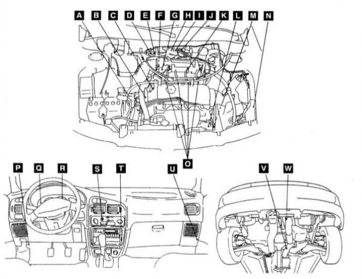
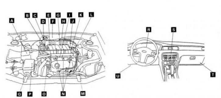
Layout of engine control components on 1.5 liter models.
A - Start enable switch (models with AT); B - Ignition distributor (with built-in CMP sensor, coil and key transistor); C - ECT sensor; D - Connector for adjusting the ignition timing; E - Control terminal of the fuel pump; F - Electric motor of the IAC system; G-TPS- (with built-in throttle closed position switch); H - MAP sensor; I - EVAP canister purge solenoid valve; J - EGR solenoid valve; K - IAT sensor; L - Power steering pressure switch (power steering); M - CKP sensor; N - The relay of coupling of the compressor K/V; O - Injector; R - Diagnostic connector DLC; Q - Warning lamp /"Check engine"; R - VSS (reed switch); S - K/V switch; T - Relay MFI; U - Engine control module (ECM); V - Heated oxygen sensor (rear); W - Heated oxygen sensor (front)
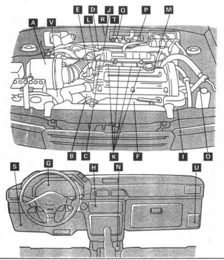
The layout of the components of the control system on models 1.6 l
A - Air flow measurement sensor (with built-in temperature and atmospheric pressure sensors); B - ECT sensor; C - TPS; D - Idle position switch; E - Crank angle sensor / TDC; F - Oxygen sensor; G - VSS (reed switch); N - K/V switch; I - Power steering pressure switch; J - EGR temperature sensor (california models); K - Injector; L - Stepper motor of the idle speed stabilization system; M - Ignition coil (key transistor); N - MPI control relay; О - Relay K / V; Р - Solenoid valve for adsorber purge; Q - EGR solenoid valve (california models); R - Terminal for adjusting the ignition timing; S - Self-diagnosis terminal; T - Control terminal of the fuel pump; U - Engine control unit; V - Start enable switch (AT)
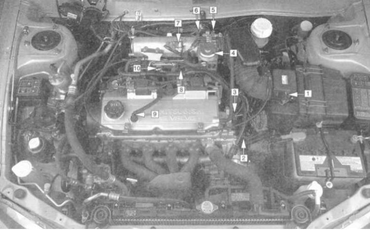
Layout of engine management/emission control system components on 1.8L models
1 - MAF sensor (with integrated IAT sensor); 2 - ECT sensor; 3 - CMP sensor; 4 - EGR valve; 5 - IAC valve (bottom of throttle body); 6 - TPS; 7 - MAP sensor; 8 - Solenoid valve for purge of the carbon adsorber of the EVAP system; 9 - PCV valve; 10 - EGR control solenoid valve
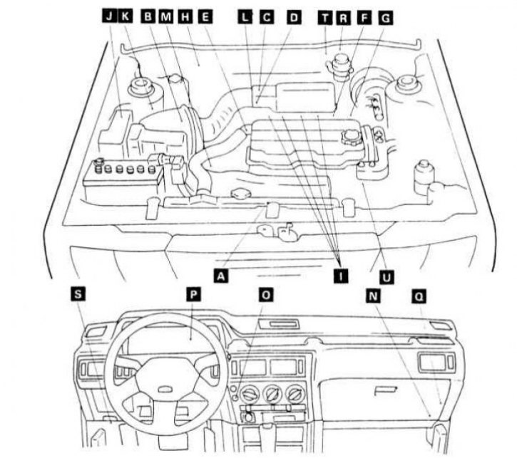
The layout of the components of the engine management system on models 2.0 l (SOHC)
A - Oxygen sensor; B - Air flow measurement sensor (by volume flow) (with built-in IAT and atmospheric pressure sensors); C - Electric motor of the idle speed stabilization system (throttle closed position switch, motor position sensor); D-TPS; E - ECT sensor; F - Ignition coil / key transistor; G - CKP/CMP sensor; H - Solenoid valve for purge of the carbon canister of the EVAP system; I - Injector; J - K/V compressor clutch relay; K - EGR solenoid valve (california models); L - EGR temperature sensor (california models); M - Sensor-switch for engine start permission (AT); N - Relay MFI; O - K/V switch; R - VSS (reed switch); Q - Engine control module (ECM); R - Terminal for adjusting the ignition timing; S - DLC diagnostic connector; T - Control terminal of the fuel pump; U - Power steering pressure switch
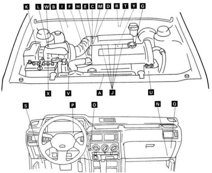
The layout of the components of the engine management system on models 2.0 l (DOHC)
A - Heated oxygen sensor; B - Air flow measurement sensor (by volume flow) (with built-in IAT and atmospheric pressure sensors); C - Stepper motor of the idle speed stabilization system; D-TPS; E - Throttle closed position switch (fixed SAS); F - ECT sensor; G - Ignition coil / key transistor; H - CKP/CMP sensor; I - EVAP canister purge solenoid valve; J - Injector; K - K/V compressor clutch relay; L - EGR solenoid valve; M - EGR temperature sensor; N - Relay MFI; O - K/V switch; R - VSS (reed switch); Q - Engine control module (ECM); R - Terminal for adjusting the ignition timing; S - DLC diagnostic connector; T - Control terminal of the fuel pump; U - Power steering pressure switch; V - Engine start enable switch (AT)
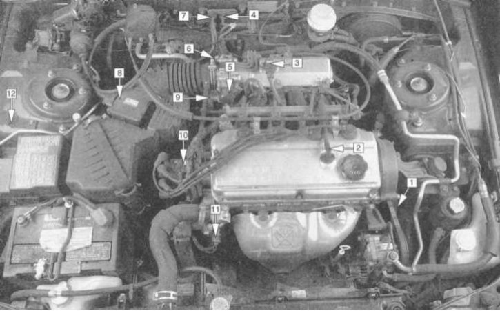
Layout of engine management/emission control system components on 2.4L models
1 - CKP sensor; 2 - PCV valve; 3 - MAP sensor; 4 - EGR solenoid valve; 5 - TPS; 6 - EGR valve (bottom of throttle body); 7 - Solenoid valve for purge of the carbon adsorber of the EVAP system; 8 - MAF sensor (with integrated IAT sensor); 9 - IAC valve (bottom of throttle body); 10 - CMP sensor (in the ignition distributor); 11 - ECT sensor; 12 - EVAP carbon adsorber (under the wheel arch mudguard)
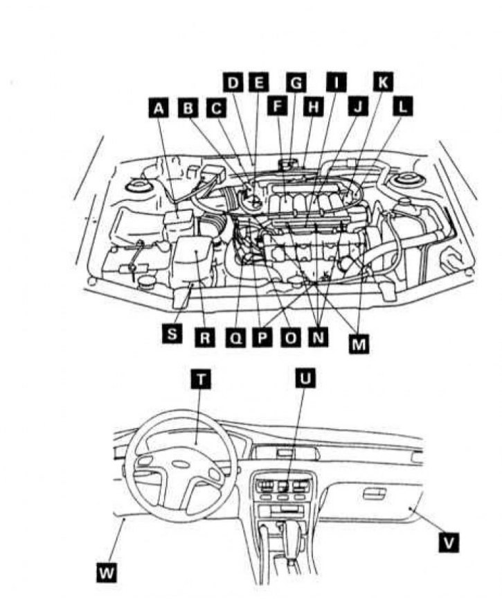
The layout of the components of the engine management system on models 3.0 l (SOHC)
A - Air flow measurement sensor (by volume flow) (with built-in IAT and atmospheric pressure sensors); B - Stepper motor of the idle speed stabilization system; C - Solenoid valve for purge of the carbon adsorber of the EVAP system; D-TPS (with built-in throttle closed position switch); E - EGR temperature sensor (all California models and federal models since 1995 vol.); F - EGR solenoid valve (all California models and federal models since 1995 vol.); G - Heated oxygen sensor; H - Terminal for adjusting the ignition timing; I - Knock sensor; J - Variable induction mixing electric motor (DC motor) (with integrated control valve position sensor); K - Ignition coil / key transistor; L - CKP/CMP sensor; M - Power steering pressure switch; N - Injector; O - ECT sensor; Р - Relay of coupling of the compressor К/В; Q - Engine start enable switch (AT); R - Warning lamp /"Check engine"; VSS (reed switch); S - K/V switch; T - Engine control module (ECM); U - Diagnostic connector
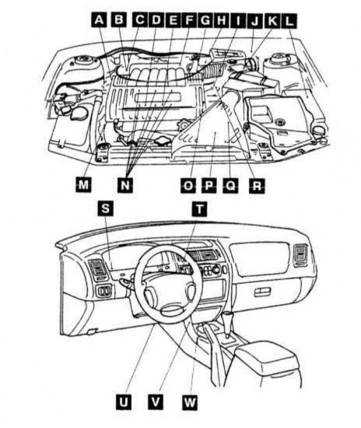
The layout of the components of the engine management system on models 3.0 l (DOHC)
A - Air flow measurement sensor (by volume flow) (with built-in IAT and atmospheric pressure sensors); B - Stepper motor of the idle speed stabilization system; C - Gas pedal position sensor (with built-in throttle closed position switch) (models equipped with tempostat); D - EVAP charcoal canister purge solenoid valve; E-TPS (models equipped with tempostat); F - EGR temperature sensor; G - EGR solenoid valve (california models); H - Terminal for adjusting the ignition timing; I - Knock sensor; J - Heated oxygen sensor; K - Electric motor of variable induction mixing (DC motor) (with integrated control valve position sensor); L - Power steering pressure switch; M - CMP sensor; N - Injector; O - ECT sensor; P - CKP sensor; Q - Ignition coil / key transistor; R - Relay clutch compressor K / V; S - Engine start enable switch (AT); T - VSS sensor (reed switch); U - K/V switch; V - Engine control module (ECM); W - Diagnostic connector
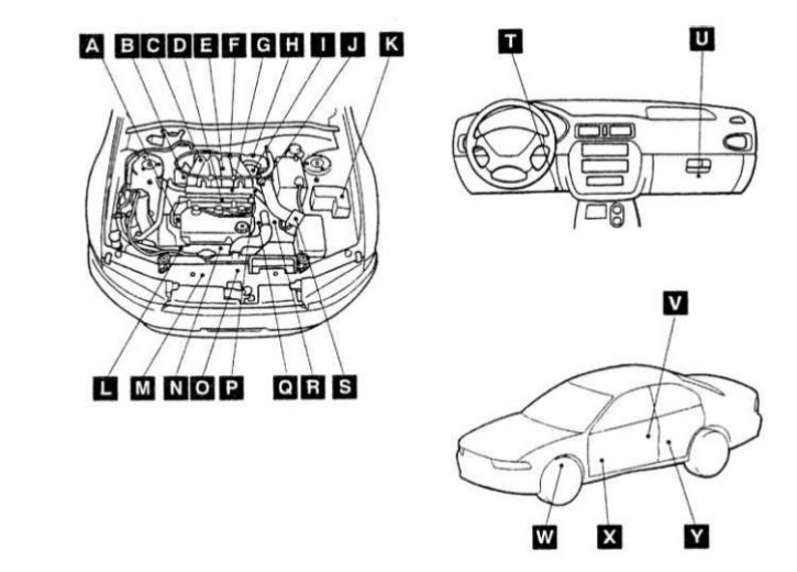
The layout of the components of the engine management system on models 3.5 l
A - Power steering pressure switch; B - Heated oxygen sensor (front); C - Heated oxygen sensor (rear); D - EVAP charcoal canister purge solenoid valve; E - EGR solenoid valve; F - Differential pressure sensor in the pipeline; G-TPS (with built-in throttle closed position switch); H - Stepper motor IAC; I - CMP sensor; J - Fuel pump control terminal; K - Air flow measurement sensor (by volume flow) (with built-in IAT and atmospheric pressure sensors); L - Clutch relay for K/V compressor; M - CKP sensor; N - Injector; O - ECT sensor; P - VSS; Q - Engine start enable switch (AT); R - Ignition coil / key transistor; S - Warning lamp failures /"Check engine"; T - K/V switch; U - Diagnostic connector DLC; V - MFI/fuel pump relay; W-ECM
The layout of the components of the engine management system on Galant models 1999-2000 3.0 l (SOHC)
A - CKP sensor; B - EGR solenoid valve; С - Heated oxygen sensor of the right row of cylinders (front) (california models); D - Knock sensor; E - Heated oxygen sensor of the right row of cylinders (rear) (california models); F - Differential pressure sensor in the pipeline; G - Injector; H - TPS; I - IAC stepper motor; J - Ignition distributor (with integrated CMP sensor and ignition coil); K - K/V compressor clutch relay; L - Power steering pressure switch; M - Heated oxygen sensor of the left row of cylinders (rear) (california models); N - Heated oxygen sensor of the left bank of cylinders (front) (california models); O - Fan controller; P - VSS; Q - ECT sensor; R - Engine start enable switch (AT); S - Air flow measurement sensor (by volume flow) (with built-in IAT and atmospheric pressure sensors); T - DLC diagnostic connector; U - PCM; V - Differential pressure sensor in the fuel tank; W - Front heated oxygen sensor (federal models); X - Rear heated oxygen sensor (federal models)
General information and precautions
Electronic systems of injection and reduction of toxicity of exhaust gases in the course of their operation during the operation of the car interact with various other systems responsible for the efficiency of the engine. All of these systems include a set of information sensors and an electronic control module (ECM/PCM).
Such systems can be compared in their structure with the central nervous system of the human body, where the role of the brain is played by an electronic control module, and information sensors act as nerve endings. The sensors send signals to the PCM, which analyzes the incoming information and generates response commands to correct the corresponding operating parameters.
Let's consider a specific example that allows us to more clearly imagine the principle of the system's functioning: an oxygen sensor built into the exhaust system continuously monitors the level of O2 in the exhaust gas stream of the engine. If the oxygen percentage noticeably deviates from some reference value stored in the system memory, the PCM immediately receives the relevant information and, based on its analysis, issues an appropriate command to adjust the duration of the opening of the fuel injection injectors, thereby adjusting the air-fuel mixture. The duration of the described procedural cycle is a fraction of a second, which ensures a high reactivity of the system. As a result, the efficiency of the engine output is constantly maintained at the highest possible level.
To avoid failure of the electronic control module (ECM/PCM), before disconnecting the electrical wiring from it, be sure to turn off the ignition and disconnect the negative cable from the battery.
Attention! If the stereo system installed in the car is equipped with a security code, before disconnecting the battery, make sure that you have the correct combination to activate the audio system!
To facilitate the introduction of the tester probes into the ECM/PCM connector when checking the input / output signals of the latter, a terminal holder follows from the connector.
When disconnecting / connecting the wiring of the control module, try not to bend or break off the contact terminals.
When measuring the supply voltage of components operating under the control of PCM, in no case allow the terminals of the tester to be shorted to each other - a short circuit in the PCM circuit can lead to an irreversible failure of the latter.
First generation OBD-I on-board self-diagnosis system
General information
One should not be mistaken in assuming that a system consisting of many different information sensors and controlled by an electronic processor is difficult to diagnose. All failures and malfunctions of the system components are recorded in the electronic memory of the control module in the form of special digital codes. Codes can be read by connecting a special scanner or digital voltmeter to the DLC diagnostic connector (see the first subsection of this Section).
Any irregularities in the functioning of the components of the injection / emission control systems are notified to the driver by actuation of the failure / warning lamp mounted in the instrument cluster"Check engine". If the failure was temporary and the control module registers the return of the system to normal operation, the warning lamp turns off. Moreover, if the ignition is turned off when the warning lamp comes on, then after the engine is started, the lamp is activated again only if the failure is re-registered by the diagnostic system.
To check the serviceability of the condition of the control lamp, its short-term operation occurs each time the ignition key is turned to the ON position. If there are no malfunctions in the engine management / emission control systems, the lamp should go out after 5 seconds. If, when the ignition is turned on, a short-term operation of the control lamp does not occur, check the condition of the wiring and the fuse of its electrical circuit, in addition, make sure that the filament of the lamp itself is intact.
Note. Failure warning lamp/"Check engine" should also work when the terminal of the connector for adjusting the ignition timing is shorted to ground.
Remember that codes register failures of electrical circuits as a whole, and not individual components included in them. So, the presence in the memory of the control module of code No. 14 indicates a malfunction in the throttle position sensor circuit (TPS), which does not necessarily indicate the failure of the sensor itself. When identifying the causes of failure, special attention should be paid to the condition of the relevant electrical wiring and the quality of its contact connections. You can eliminate the possibility of failure of the working element of the circuit, or you can make sure of it by substituting a known-good component.
In the memory of the on-board diagnostics processor (PCM) codes of many different faults can be stored at the same time. The issuance of codes during reading is carried out in ascending order of their identification numbers and does not depend in any way on the order in which they were entered into memory.
Before reading diagnostic codes, make sure that the voltage generated by the battery complies with regulatory requirements (see chapter Engine electrical equipment).
Remember that when you disconnect the wiring from the battery or the engine management system controller, the OBD memory is automatically cleared!
Before connecting the reader to the DLC diagnostic connector and disconnecting it, do not forget to turn the ignition key to the OFF position. Performing these operations with the ignition on may cause false diagnostic codes to be entered into the processor memory (at the same time, the failure indicator lamp /"Check engine".
Reading trouble codes with a scanner
Attention! Below is a description of the procedure for reading codes from the ECM memory using a Mitsubishi MUT-II type scanner. When using devices manufactured by other manufacturers, strictly follow the enclosed instructions!
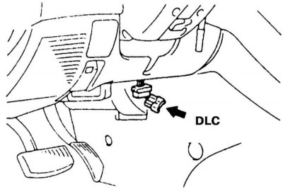
1. Connect the scanner to the DLC diagnostic connector located on the left under the instrument panel (if necessary, first remove the access cover).
Note. On Galant models, the DLC connector can be located inside the glove box, to the right of its lock assembly.
 | 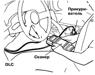 |
2. Follow the manufacturer's instructions to read and record the output from the scanner.
3. Diagnose the condition of the relevant components and their electrical circuits, perform the necessary refurbishment/replace defective components.
4. Turn the key to the OFF position, then turn the ignition back on.
5. Clear the OBD processor memory (see below).
6. After repeating the reading procedure, make sure that the code for the normal functioning of the system is present in the OBD memory.
Reading trouble codes with an analog voltmeter
1. If equipped, remove the DLC connector access cover.
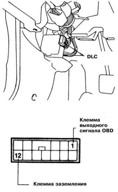
2. Connect an analog voltmeter between the ground and OBD signal output terminals of the DLC connector.
3. Turn on the ignition.
4. Read and write down the signal sequence given out by the voltmeter.
5. Diagnose the condition of the relevant components and their electrical circuits, perform the necessary refurbishment/replace defective components.
6. Clear the OBD processor memory (see below).
Clearing CPU Memory
Note. When clearing processor memory using a scanner-type reader, follow the device manufacturers' instructions.
1. Turn off the ignition.
2. Disconnect the negative cable from the battery.
Attention! If the stereo system installed in the car is equipped with a security code, before disconnecting the battery, make sure that you have the correct combination to activate the audio system! Reconnect the battery after at least 1 minute.
3. Turn on the ignition.
4. Having completed the reading procedure, make sure that the code for the normal functioning of the system is present in the OBD memory.
List of fault codes
| code no | The element in the contour of which there is a violation |
| 11 | Oxygen sensor |
| 12 | Air flow measurement sensor |
| 13 | intake air temperature sensor (IAT) |
| 14 | Throttle position sensor |
| 15 | Motor Position Sensor SC (MPS) |
| 21 | coolant temperature sensor (ECT) |
| 22 | RPM/Crank Angle Sensor |
| 23 | Camshaft position sensor (CMP) / TDC of the first cylinder |
| 24 | Movement speed sensor (VSS) |
| 25 | Atmospheric pressure sensor (BARO) |
| 31 | Knock sensor |
| 32 | Pipe pressure sensor (MAP) |
| 36 | Ignition timing signal |
| 39 | Oxygen sensor (rear - turbocharged models) |
| 41 | Injector |
| 42 | Fuel pump |
| 43 | EGR (california models) |
| 44 | Ignition Coil/Switch Transistor (cylinders No. 1 and 4) - 3.0 l models |
| 52 | Ignition Coil/Switch Transistor (cylinders No. 2 and 5) - 3.0 l models |
| 53 | Ignition Coil/Switch Transistor (cylinders No. 3 and 6) - 3.0 l models |
| 54 | Anti-theft system |
| 55 | A/C damper position sensor (or control activator x.x. [ISC]) |
| 59 | Heated oxygen sensor |
| 61 | AT control unit cable |
| 62 | Start flap position sensor (non-turbo models) |
| 64 | Generator |
| 71 | Vacuum e/magnetic valve of traction control system |
| 72 | E / magnetic vent valve anti-slip system |
| 0 | No faults in memory |
Second generation OBD-II on-board self-diagnosis system
General information
Onboard processor (PCM) is responsible for the proper functioning of the components of the exhaust gas toxicity reduction systems, cooling system fans, can adjust the ignition timing and control the operating parameters of the automatic transmission. The subordination of the power supply and ignition systems to one control module allows for fine adjustments of the composition of the air-fuel mixture under any engine operating conditions. The general principles of PCM operation are described in the second subsection of this Section.
In addition to its control functions, the PCM also continuously monitors the status of engine management/emission control components, making it the centerpiece of the on-board self-diagnosis system. Electrical failure codes of various circuits of the corresponding subsystems and elements are recorded in the processor memory.
It should be noted that the second generation on-board diagnostic system is not capable of registering violations of a mechanical or hydrodynamic nature, however, such failures can be recorded directly due to the influence exerted on the functioning of electrical components. So, OBD is physically unable to detect such a defect as a partial violation of the injector patency, however, the result of this violation will invariably be recorded by the fact that the air-fuel mixture is depleted, indirectly recorded by the oxygen sensor. Based on the analysis of the signals coming from the O2 sensor, the system control module will write the corresponding diagnostic code to the processor memory.
A distinctive feature of second-generation self-diagnosis systems (OBD-II) is the organization of adaptive logic in them, which makes it possible to dynamically control the functioning of the fuel injection system. This feature allows you to automatically compensate for wear and fluctuations in the parameters of the components of the power system. Thus, with a stable engine running, the control module monitors the trend towards lean or rich air-fuel mixture and takes appropriate steps to adjust its composition, trying to constantly maintain a stoichiometric ratio of 14.7:1. Corrective parameters are entered into a special memory of the processor, fixed in it and remain available during subsequent cycles of vehicle operation (the memory is powered directly from the battery and does not depend on the position of the ignition switch).
Reading trouble codes with a scanner
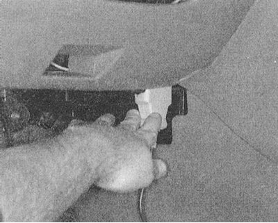
1 The scanner is connected to the diagnostic connector located on the left under the instrument panel (DLC).
2. The first step in diagnosing a system is always to poll the control module memory. At this stage, the general nature of failures is determined, and sequential reading of codes makes it possible to reveal the fact of their removal from memory.
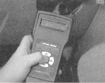
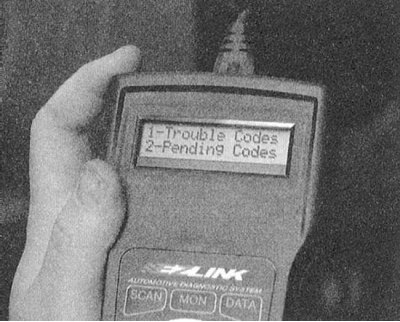
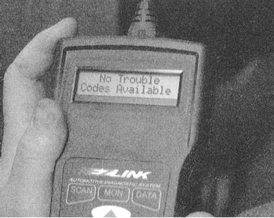
3. To read the codes, both the branded scanner of the car manufacturer and third-party scanners can be used - strictly follow the instructions of the device manufacturers.
 |  |
Reading trouble codes with a voltmeter
1. Find the DLC diagnostic connector on the left under the instrument panel.
2. On models since 1996, no. it is possible to switch between arbitration and federal formats for reading codes. Usually on models equipped with the 2nd generation on-board self-diagnosis system (OBD-II) ability to read surge codes ("outbreaks") DLC is not provided on the terminals of the connector and the use of a scanner is a prerequisite, however, this feature is implemented on Mitsubishi models.
3. Due to the global standardization of OBD-II codes, their decryption is greatly simplified. When reading codes with a voltmeter (on voltage surges at the DLC terminals) the first two positions of the designation are not used. Due to the fact that the car's gearbox is one of the components of the transmission line, its failure codes also begin with the letter P. In addition, since there is no match between the Mitsubishi and SAE code numbers, the code digit following the letter also does not matter.
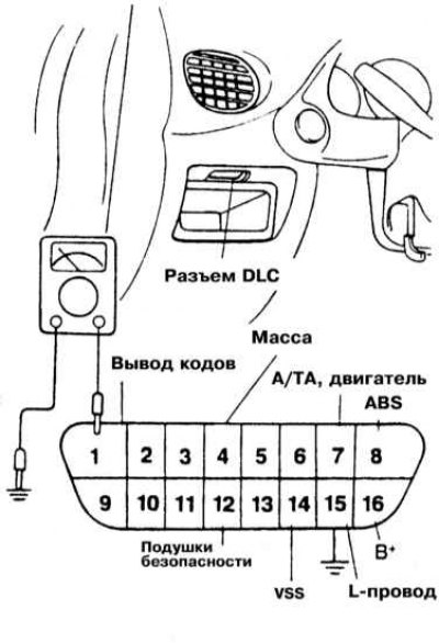
4. Codes can be read from the flicker of a voltmeter connected to the DLC connector. Each code is displayed in a series of three groups "outbreaks". So, the code P0753 corresponds to a group of" seven flashes", followed immediately by groups of five and three "outbreaks". The display of the next code starts after a short pause. duration of all "outbreaks" the same, the only exception is zero, indicated by a voltage surge of longer duration; so the code is P0702 (short circuit in TPS circuit) will look like this: seven normal "outbreaks", one long, then two more normal.
5. Reading codes is done as follows:
- Make sure that the electrical wiring and its contact connections are in good condition;
- Prepare paper and pencil for taking notes;
- Find the DLC diagnostic connector on the left under the car's dashboard;
- Start the engine and drive the vehicle for a short time to enter the system into self-diagnostic mode;
- Park the car, leaving the engine running at idle;
- Connect Voltmeter (analog or digital) to the terminals of the DLC diagnostic connector, - positive wire to terminal 1, negative to terminal 4;
- Following the throws of the arrow / jumps in readings, read the fault codes recorded in the processor memory (see below). Write down the results; Sometimes it is also possible to read codes by flashing a control lamp "Check engine" after closing terminal 1 of the connector to the housing.
- Make the necessary corrections, clear the processor memory and, by repeating the test, make sure that there are no codes in the memory.
Clearing CPU Memory
1. Clearing the processor memory after troubleshooting must be done without fail.
2. For cleaning, use the GST scanner or a special tester.
3. To clear the ECM memory, connect a scanner to the system and in its menu layout, select the function "CLEARING COEDS" ("Deleting codes"). Then follow the instructions displayed on the device. Alternatively, system memory can be cleared by disconnecting the battery.
Attention! If the stereo system installed in the car is equipped with a security code, before disconnecting the battery, make sure that you have the correct combination to activate the audio system!
Disconnecting the battery also deletes the receiver's favorite radio stations.
To avoid damage to the ECM, disconnect and connect it only with the ignition off!
List of fault codes
SAE codes readable with a scanner, or with a voltmeter or LED (only the three least significant digits of the code).
| P0000 | No trouble codes in system memory |
| P0100 | Violation in the circuit of the MAF air mass meter / absolute pressure sensor in the pipeline (MAP) |
| P0101 | Faulty MAF sensor |
| P0102 | Short to the body or low signal level of the MAF / MAP sensor |
| P0103 | Short circuit to or high signal level of the MAF / MAP sensor |
| P0104 | Intermittent malfunction of the MAF sensor |
| P0105 | Malfunctions in the absolute pressure sensor circuit (IDA) / barometric sensor |
| P0106 | Malfunction of the absolute pressure sensor (IDA) / barometric sensor |
| P0107 | Open or short circuit to the case of the MAP / Barometric sensor circuit |
| P0108 | Short circuit in the MAP / Barometric sensor circuit |
| P0109 | Intermittent malfunction of the MAP sensor / barometric pressure sensor |
| P0110 | Violation in the intake air temperature sensor circuit (IAT) |
| P0111 | Violation of serviceability of functioning of gauge IAT |
| P0112 | IAT sensor circuit short to case |
| P0113 | Open or short circuit in the IAT sensor circuit |
| P0114 | Intermittent IAT sensor function error |
| P0115 | Absence or excessively low coolant temperature sensor signal (EATING) |
| P0116 | Excessively high ECT sensor signal level / engine efficiency problems |
| P0117 | Short circuit of a chain of the ECT sensor on the case |
| P0118 | Open or short circuit in the sensor circuit |
| P0119 | Intermittent sensor error |
| P0120 | Malfunctions in the throttle position sensor circuit (TPS) / switch A |
| P0121 | Violation in the TPS / switch A circuit; Reduced engine recoil efficiency |
| P0122 | TPS Sensor/Pedal Position Sensor A Low Input |
| P0123 | TPS Sensor/Pedal Position Sensor A High Input |
| P0124 | Intermittent TPS Sensor/Switch A Function Error |
| P0125 | The coolant temperature is insufficient for proper functioning of the feedback in the fuel control circuit |
| P0126 | The coolant temperature is insufficient for stable operation of the control system |
| P0130 | Malfunction in the chain of the upper flow l-probe (right row of cylinders on a V-shaped engine) |
| P0131 | High Flow Heated l-Probe Circuit Low Voltage (right row of cylinders on a V-shaped engine) |
| P0132 | High voltage upstream heated l-probe (right row of cylinders on a V-shaped engine) |
| P0133 | Excessively high voltage or slow response of the upstream heated l-probe (right row of cylinders on a V-shaped engine) |
| P0134 | No signal from the upper flow l-probe (right row of cylinders on a V-shaped engine) |
| P0135 | Violation in the heating circuit of the upper flow l-probe (excessively high voltage) (right row of cylinders on a V-shaped engine) |
| P0136 | Violation in the chain of the lower-flow heated l-probe (excessively low voltage) (right row of cylinders on a V-shaped engine) |
| P0137 | Heated low-flow l-probe circuit low voltage (right row of cylinders on a V-shaped engine) |
| P0138 | Excessively high voltage of the low-flow heated l-probe circuit (right row of cylinders on a V-shaped engine) |
| P0139 | Slow response of downstream heated l-probe (right row of cylinders on a V-shaped engine) |
| P0140 | High voltage or malfunction of the low-flow l-probe (right row of cylinders on a V-shaped engine) |
| P0141 | Violation in the heating circuit of the lower-flow l-probe (right row of cylinders on a V-shaped engine) |
| P0142 | Faulty l-probe 3 (right row of cylinders on a V-shaped engine) |
| P0143 | Low voltage l-probe 3 (right row of cylinders on a V-shaped engine) |
| P0144 | High voltage l-probe 3 (right row of cylinders on a V-shaped engine) |
| P0145 | Reduced reactivity l-probe 3 (right row of cylinders on a V-shaped engine) |
| P0146 | Violation of the activity of functioning of the l-probe 3 (right row of cylinders on a V-shaped engine) |
| P0147 | Faulty l-probe heating 3 (right row of cylinders on a V-shaped engine) |
| P0150 | Malfunction in the chain of the upper flow l-probe (left row of cylinders on a V-shaped engine) |
| P0151 | Violation of serviceability of functioning of tracking of depletion of a mixture of an upper flow l-probe (left row of cylinders on a V-shaped engine) |
| P0152 | Upstream l-probe enrichment tracking failure (left row of cylinders on a V-shaped engine) |
| P0153 | Slow response of the upper flow l-probe (left row of cylinders on a V-shaped engine) |
| P0154 | High voltage upper flow l-probe (left row of cylinders on a V-shaped engine) |
| P0155 | Violation of serviceability of functioning of the heater of the upper-flow l-probe (left row of cylinders on a V-shaped engine) |
| P0156 | Downstream l-probe defective (left row of cylinders on a V-shaped engine) |
| P0157 | Low voltage low flow l-probe (left row of cylinders on a V-shaped engine) |
| P0158 | Low flow l-probe high voltage (left row of cylinders on a V-shaped engine) |
| P0159 | Slow response downstream l-probe (right row of cylinders on a V-shaped engine) |
| P0160 | No signal from the downstream l-probe (left row of cylinders on a V-shaped engine) |
| P0161 | Violation of serviceability of functioning of the heater of the lower-flow l-probe (right row of cylinders on a V-shaped engine) |
| P0162 | Faulty l-probe 3 (left row of cylinders on a V-shaped engine) |
| P0163 | Low voltage l-probe 3 (left row of cylinders on a V-shaped engine) |
| P0164 | High voltage l-probe 3 (left row of cylinders on a V-shaped engine) |
| P0165 | Reduced reactivity l-probe 3 (left row of cylinders on a V-shaped engine) |
| P0166 | Violation of the activity of functioning of the l-probe 3 (left row of cylinders on a V-shaped engine) |
| P0167 | Faulty l-probe heating 3 (left row of cylinders on a V-shaped engine) |
| P0170 | Re-leaning or re-enriching the air-fuel mixture (right row of cylinders on a V-shaped engine) |
| P0171 | Re-leaning of the air-fuel mixture (right row of cylinders on a V-shaped engine) |
| P0172 | Re-enrichment of the air-fuel mixture (right row of cylinders on a V-shaped engine) |
| P0173 | Re-lean or re-enriched injection (left row of cylinders on a V-shaped engine) |
| P0174 | Re-lean injection (left row of cylinders on a V-shaped engine) |
| P0175 | Re-enriched injection (left row of cylinders on a V-shaped engine) |
| P0176 | Malfunction in a chain of the gauge of composition of fuel |
| P0177 | Serviceability of functioning of the gauge of structure of fuel is broken |
| P0178 | Short to ground in the fuel composition sensor circuit |
| P0179 | Short circuit on in a chain of the sensor of composition of fuel |
| P0180 | Malfunction in a chain of the gauge A of temperature in a fuel tank |
| P0181 | Serviceability of functioning of the gauge A of temperature of fuel is broken |
| P0182 | Short to ground in fuel temperature sensor A circuit |
| P0183 | Short circuit on in a chain of the gauge And temperature of fuel |
| P0184 | Intermittent malfunction in the fuel temperature sensor A circuit |
| P0185 | Malfunction in a chain of the gauge B of temperature of fuel |
| P0186 | Serviceability of functioning of the sensor B of temperature of fuel is broken |
| P0187 | Short to ground in fuel temperature sensor B circuit |
| P0188 | Short circuit on in a chain of the sensor B of temperature of fuel |
| P0189 | Intermittent fault in fuel temperature sensor B circuit |
| P0190, P0191 | The function of the injection pressure sensor is broken (on the fuel line) |
| P0192 | Injection pressure sensor voltage too low |
| P0193 | Injection pressure sensor voltage too high |
| P0194 | Intermittent malfunction in the fuel line pressure sensor circuit |
| P0195 | Malfunction in a chain of the sensor of temperature of motive oil |
| P0196 | Serviceability of functioning of the gauge of temperature of impellent oil is broken |
| P0197 | Short to ground in the engine oil temperature sensor circuit |
| P0198 | Short circuit on in a chain of the sensor of temperature of impellent oil |
| P0199 | Intermittent malfunction in the engine oil temperature sensor circuit |
| P0200 | Malfunction in a chain of injection of fuel |
| P0201-P0206 | Malfunction in a chain of an injector of the cylinder 1 - 6 respectively |
| P0214 | Violation of serviceability of functioning of an injector of cold start 2 |
| P0215 | Violation of serviceability of functioning of the locking electromagnetic valve |
| P0216 | Malfunction in a chain of management of distribution of injection of fuel |
| P0217 | Engine overheating |
| P0218 | Transmission overheating |
| P0219 | Inadmissible excess of turns of the engine |
| P0220 | Malfunction in a chain TPS / sensor-switch B |
| P0221 | Violation of serviceability of functioning of TPS / sensor-switch B |
| P0222 | Short to ground in the TPS circuit / sensor-switch B |
| P0223 | Short circuit on in TPS chain / sensor-switch B |
| P0224 | Intermittent TPS/Switch B Fault |
| P0225 | Malfunction in the TPS circuit / sensor-switch |
| P0226 | Violation of serviceability of functioning of TPS / gauge-switch |
| P0227 | Short to ground in the TPS circuit / sensor-switch |
| P0228 | Short circuit on in a chain TPS / the gauge switch |
| P0229 | Intermittent TPS/switch fault |
| P0230 | Malfunction in a chain of a primary contour of the fuel pump |
| P0231 | Short circuit on weight in a chain of a secondary contour of the fuel pump |
| P0232 | Short circuit on in a chain of a secondary contour of the fuel pump |
| P0233 | Intermittent malfunction in the secondary circuit of the fuel pump |
| P0261 | Short circuit on weight in a chain of an injector of injection of cylinder 1 |
| P0262 | Short circuit on in a chain of an injector of injection of cylinder 1 |
| P0263 | Injection imbalance in cylinder 1 injector |
| P0264 | Short circuit on weight in a chain of an injector of injection of cylinder 2 |
| P0265 | Short circuit on in a chain of an injector of injection of cylinder 2 |
| P0266 | Injection imbalance in cylinder 2 injector |
| P0267 | Short circuit on weight in a chain of an injector of injection of cylinder 3 |
| P0268 | Short circuit on in a chain of an injector of injection of cylinder 3 |
| P0269 | Injection imbalance in cylinder 3 injector |
| P0270 | Short circuit on weight in a chain of an injector of injection of cylinder 4 |
| P0271 | Short circuit on in a chain of an injector of injection of cylinder 4 |
| P0272 | Injection imbalance in cylinder 4 injector |
| P0273 | Short circuit on weight in a chain of an injector of injection of cylinder 5 |
| P0274 | Short circuit on in a chain of an injector of injection of cylinder 5 |
| P0275 | Injection imbalance in cylinder 5 injector |
| P0276 | Short circuit on weight in a chain of an injector of injection of the cylinder 6 |
| P0277 | Short circuit on in a chain of an injector of injection of the cylinder 6 |
| P0278 | Injection imbalance in cylinder 6 injector |
| P0300 | Random misfiring occurs in various cylinders |
| P0301-P0308 | There are misfires in cylinder 1 - 8, respectively |
| P0320, P0321 | Malfunction in the input circuit of the engine speed control circuit of the ignition distribution control system |
| P0322 | No signal in the input circuit of the engine speed control circuit of the ignition distribution control system |
| P0323 | Intermittent malfunction in the input circuit of the engine speed control circuit of the ignition distribution control system |
| P0325 | Faulty knock sensor 1 (right row of cylinders on a V-shaped engine) |
| P0326 | Faulty knock sensor 1 (right row of cylinders on a V-shaped engine) |
| P0327 | Short circuit on the case of a chain of the gauge of a detonation 1 (right row of cylinders on a V-shaped engine) |
| P0328 | Short circuit on a chain of the sensor of a detonation 1 (right row of cylinders on a V-shaped engine) |
| P0329 | Intermittent fault in knock sensor 1 input circuit |
| P0330 | Faulty knock sensor 2 (left row of cylinders on a V-shaped engine) |
| P0331 | Faulty knock sensor 2 (left row of cylinders on a V-shaped engine) |
| P0332 | Short to ground knock sensor 2 circuit (left row of cylinders on a V-shaped engine) |
| P0333 | Short circuit on in a chain of the gauge of a detonation 2 (left row of cylinders on a V-shaped engine) |
| P0334 | Intermittent fault in knock sensor 2 input circuit (left row of cylinders on a V-shaped engine) |
| P0335 | Engine speed signal / Malfunction in the sensor circuit A of the position of the crankshaft SKR |
| P0336 | Crankshaft Position Sensor A |
| P0337 | A short to the body in the SKR sensor circuit A |
| P0338 | Short circuit on in a chain of the SKR sensor And |
| P0339 | Intermittent malfunction in the CKP A sensor circuit |
| P0340 | Malfunction in a chain of the gauge of provision of a camshaft SMR |
| P0341 | Violation of serviceability of functioning of the CMR sensor |
| P0342 | Short to ground in the CMP sensor circuit |
| P0343 | Short circuit on in a chain of the CMP sensor |
| P0344 | Intermittent malfunction in the CMP sensor circuit |
| P0350 | Malfunction in the primary / secondary circuit of the ignition coil |
| P0351-P0362 | Malfunction in the primary / secondary circuit of the ignition coil A - L, respectively |
| P0370 | Malfunction in a chain of a reference signal of a high resolution A of management of installation of an angle of an advancing of ignition |
| P0371 | Malfunction in a chain of a reference signal of a high resolution A of management of installation of an angle of an advancing of ignition (excessive impulses) |
| P0372 | Malfunction in a chain of a reference signal of a high resolution A of management of installation of an angle of an advancing of ignition (not enough impulses) |
| P0373 | Intermittent fault in high resolution reference signal circuit A ignition timing control (pulse arrhythmia) |
| P0374 | Malfunction in a chain of a reference signal of a high resolution A of management of installation of an angle of an advancing of ignition (lack of impulses) |
| P0375 | Malfunction in a chain of a reference signal of a high resolution In managements of installation of an angle of an advancing of ignition |
| P0376 | Malfunction in a chain of a reference signal of a high resolution In managements of installation of an angle of an advancing of ignition (excessive impulses) |
| P0377 | Malfunction in a chain of a reference signal of a high resolution In managements of installation of an angle of an advancing of ignition (not enough impulses) |
| P0378 | Intermittent fault in high resolution reference circuit B ignition timing control (pulse arrhythmia) |
| P0379 | Malfunction in a chain of a reference signal of a high resolution In managements of installation of an angle of an advancing of ignition (lack of impulses) |
| P0385 | Malfunction in a chain of the SKR sensor In |
| P0386 | Violation of the serviceability of the functioning of the sensor SKR B |
| P0387 | Short to ground in the SKR sensor circuit B |
| P0388 | Short circuit on in a chain of the SKR sensor In |
| P0389 | Intermittent malfunction in the CKP B sensor circuit |
| P0400 | Excessive or insufficient intensity of exhaust gas recirculation (EGR) |
| P0401 | Decreased EGR flow detected |
| P0402 | Excessive increase in EGR flow detected Malfunction in the EGR back pressure sensor circuit |
| P0403 | Malfunction in the EGR valve circuit |
| P0404 | Violation of serviceability of functioning of chain EGR |
| P0405 | Short to ground in EGR sensor A circuit |
| P0406 | Short circuit on in a chain of gauge And EGR |
| P0407 | Short to ground in sensor circuit B EGR |
| P0408 | Short circuit on in a chain of the gauge In EGR |
| P0410 | Malfunction in system of admixture of additional air |
| P0411 | Incorrect determination of the flow by the auxiliary air mixing system |
| P0412 | Malfunction in a chain of the valve A of system of admixture of additional air |
| P0413 | Open or short circuit in the valve circuit A of the additional air mixing system |
| P0414 | Short circuit on the case of a chain of the valve A of system of admixture of additional air |
| P0415 | Malfunction in a chain of the valve-switch In systems of admixture of additional air |
| P0416 | An open in the switch valve circuit B of the additional air mixing system |
| P0417 | Short circuit in the valve-switch circuit In the additional air mixing system |
| P0418 | Infringement of serviceability of functioning of the relay A of system of admixture of additional air |
| P0419 | Infringement of serviceability of functioning of the relay In systems of admixture of additional air |
| P0420-P0423 | Violation of serviceability of functioning of the catalytic converter (right row of cylinders on a V-shaped engine) |
| P0424 | Excessive decrease in temperature of the catalytic converter (right row of cylinders on a V-shaped engine) |
| P0430-P0433 | Excessively reduced efficiency of the catalytic converter (left row of cylinders on a V-shaped engine) |
| P0434 | Excessive decrease in temperature of the catalytic converter (left row of cylinders on a V-shaped engine) |
| P0440 | EVAP Evaporative Emission System Leaks |
| P0441 | Faulty VSV of the EVAP system |
| P0442 | Minor leak found in EVAP system |
| P0443-P0446 | Malfunction in a chain of the valve of management of a purge of a coal adsorber EVAP |
| P0447 | An open in the EVAP ventilation control circuit |
| P0448 | Short in EVAP ventilation control circuit |
| P0449 | Malfunction in a chain of the electromagnetic valve / valve of ventilation of system EVAP |
| P0450 | Violation in the vapor pressure sensor circuit in the gas tank of the EVAP system |
| P0451 | Violation of serviceability of functioning of system EVAP |
| P0452 | Low fuel tank pressure sensor input (EVAP system) |
| P0453 | Fuel Tank Pressure Sensor High Input (EVAP system) |
| P0454 | EVAP Pressure Sensor Intermittent Malfunction |
| P0455 | Significant leak detected in EVAP system |
| P0460 | Malfunction in a chain of the gauge of level of fuel |
| P0461 | Violation of serviceability of functioning of the gauge of level of fuel |
| P0462 | Short to ground in the fuel level sensor circuit |
| P0463 | Short circuit on in a chain of the gauge of level of fuel |
| P0464 | Intermittent malfunction in the fuel level sensor circuit |
| P0465 | Malfunction in a chain of the gauge of a stream of a purge |
| P0466 | Violation of serviceability of functioning of the gauge of a stream of a purge |
| P0467 | Short to ground in the purge flow sensor circuit |
| P0468 | Short circuit on in a chain of the sensor of a stream of a purge |
| P0469 | Intermittent failure of the purge flow sensor |
| P0470 | Malfunction in a chain of the gauge of pressure of the fulfilled gases |
| P0471 | Infringement of serviceability of functioning of the gauge of pressure of the fulfilled gases |
| P0472 | Short to ground in the exhaust gas pressure sensor circuit |
| P0473 | Short circuit on in a chain of the gauge of pressure of the fulfilled gases |
| P0474 | Intermittent malfunction in the exhaust gas pressure sensor circuit |
| P0475 | Malfunction in a chain of the operating valve of pressure of the fulfilled gases |
| P0476 | Violation of serviceability of functioning of the operating valve of pressure of the fulfilled gases |
| P0477 | Short circuit on weight in a chain of the operating valve of pressure of the fulfilled gases |
| P0478 | Short circuit on in a chain of the operating valve of pressure of the fulfilled gases |
| P0479 | Intermittent fault in the exhaust gas pressure control valve circuit |
| P0480 | Malfunction in a chain of management of the fan 1 of system of cooling |
| P0481 | Malfunction in a chain of management of the fan 2 of the cooling system |
| P0482 | Malfunction in a chain of management of the fan 3 of system of cooling |
| P0483 | Failure to check the rationality of the operation of the cooling fan |
| P0484 | Overcurrent in the cooling fan circuit |
| P0485 | Malfunction in the power / ground circuit of the cooling fan |
| P0500, P0501 | Malfunction in a chain of the gauge of speed of the car VSS |
| P0502 | No signal or short to VSS sensor housing |
| P0503 | Instability / irregular rhythm / signal overestimation in VSS operation |
| P0505 | Malfunction in a chain of gauge IAC of stabilization of turns of idling |
| P0506 | Unexpected underestimation of the engine speed when the idle speed stabilization system is activated |
| P0507 | Unexpected overspeed of the engine when the idle speed stabilization system is activated |
| P0510 | Malfunction in a chain d / in the closed position of the throttle valve TPS |
| P0520 | Malfunction in a chain of the gauge/sensor-switch of pressure of motive oil |
| P0521 | Violation of serviceability of functioning of the sensor / sensor-switch of pressure of motive oil |
| P0522 | Short circuit on weight in a chain of the gauge/sensor-switch of pressure of motive oil |
| P0523 | Short circuit on in a chain of the gauge / the gauge switch of pressure of impellent oil |
| P0530 | Infringement of a chain of the gauge of pressure of a refrigerant of system K/V |
| P0531 | Infringement of serviceability of functioning of the gauge of pressure of a refrigerant of system К/В |
| P0532 | Short circuit on weight in a chain of the gauge of pressure of a refrigerant of system K/V |
| P0533 | Short circuit on in a chain of the gauge of pressure of a refrigerant of system K/V |
| P0534 | Discharge (loss of refrigerant) in the cooling circuit of the A/C system |
| P0535 | Absence or instability of the engine speed signal - ignition |
| P0550 | Malfunction in the pressure sensor circuit of the PAS system (power steering) |
| P0551 | Violation of serviceability of functioning of the gauge of pressure of system PAS (power steering) |
| P0552 | Short to ground in the PAS pressure sensor circuit (power steering) |
| P0553 | Short circuit on in a chain of the gauge of pressure of the PAS system (power steering) |
| P0554 | Intermittent malfunction in the PAS pressure sensor circuit (power steering) |
| P0560 | Malfunction in the onboard power supply system |
| P0561 | Violation of the stability of the on-board power supply voltage |
| P0562 | Undervoltage of the onboard power supply |
| P0563 | Overvoltage of the onboard power supply |
| P0565 | Violation in the generation of the tempostat switch-on signal |
| P0566 | Violation in the generation of the tempostat switch-off signal |
| P0567 | Violation in the generation of a return signal (RESUME) tempostat |
| P0568 | Violation in the generation of the installation signal (SET) tempostat |
| P0569 | Violation in the development of a coasting signal (CAST) tempostat |
| P0570 | Violation in the development of the acceleration signal (ACCEL) tempostat |
| P0571 | Malfunction in a chain of the gauge-switch A of braking of a tempostat |
| P0572 | Short to ground in the sensor-switch circuit A for braking the tempostat |
| P0573 | Short circuit on in a chain of the sensor-switch A of braking of a tempostat |
| P0574-P0580 | Backup zone of the speed control system (tempostat) |
| P0600 | Malfunction of the serial port of the control unit AT |
| P0601 | Error in calculating the checksum of the control module memory |
| P0602 | Control module programming error |
| P0603 | Memory refresh error (KAM) control module |
| P0604 | RAM error (RAM) control module |
| P0605 | ROM error (ROM) control module |
| P0606 | PCM processor failure |
| P0608 | Violation in the development of output signal A of the VSS control module |
| P0609 | Violation in the development of the output signal In the control module VSS |
| P0620 | Malfunction in a chain of management of the generator |
| P0621 | Malfunction in a chain of management L of a control lamp of the generator |
| P0622 | Malfunction in the field circuit F of the generator control |
| P0650 | Malfunction in a chain of a control lamp of failures (MIL) |
| P0654 | Malfunction in a chain of an output signal of turns of the engine |
| P0655 | Malfunction in a chain of an output signal of a control lamp of an overheat of the engine |
| P0656 | Malfunction in a chain of an output signal of level of fuel |
| P0700 | Violation of serviceability of functioning of a control system of transmission |
| P0701 | Malfunction in a chain of an output signal of turns of the AT engine |
| P0702 | Electric malfunction in a chain of a control system of transmission |
| P0703 | Malfunction in a chain of the gauge-switch In braking / converter of rotation |
| P0704 | Malfunction in an input contour of a chain of the gauge switch of coupling |
| P0705 | Malfunction in a chain of the gauge switch of position of transmission |
| P0706 | Malfunction in a chain of the gauge switch of position of transmission |
| P0707 | Short circuit on weight in a chain of the gauge-switch of positions of transmission |
| P0708 | Short circuit on in a chain of the gauge-switch of positions of transmission |
| P0709 | The alternating malfunction in a chain of the gauge-switch of positions of transmission |
| P0710 | Malfunction in a chain of the sensor of temperature ATF |
| P0711 | Malfunction in a chain of the sensor of temperature ATF |
| P0712 | Short to ground in the ATF temperature sensor circuit |
| P0713 | Short circuit on in a chain of the sensor of temperature ATF |
| P0714 | Intermittent malfunction in the ATF temperature sensor circuit |
| P0715 | Malfunction in the input circuit of the turbine speed sensor circuit |
| P0716 | Malfunction in the input circuit of the turbine speed sensor circuit |
| P0717 | Lack of signal in the input circuit of the turbine speed sensor circuit |
| P0718 | Intermittent malfunction in the input circuit of the turbine speed sensor circuit |
| P0719 | Short circuit on weight in a chain of the gauge-switch In braking / converter of rotation |
| P0720 | Malfunction in a chain of the gauge of turns |
| P0721 | Violation of serviceability of functioning of the gauge of turns |
| P0722 | No rpm sensor output |
| P0723 | Intermittent RPM Sensor Malfunction |
| P0724 | Short circuit on in a chain of the gauge-switch In braking / converter of rotation |
| P0725 | Malfunctions in giving a signal of turns of the engine |
| P0726 | Malfunction in an input contour of a chain of registration of turns of the engine |
| P0727 | No input signal in the engine speed detection circuit |
| P0728 | Intermittent malfunction in the input circuit of the engine speed detection circuit |
| P0730 | Incorrect AT gear selection |
| P0731-P0735 | Malfunctions in the supply of the signal for switching on 1 - 5th gear, respectively |
| P0736 | Malfunctions in giving of a signal of inclusion of a reverse gear |
| P0740 | Malfunction in the solenoid circuit of the TCC AT valve |
| P0741 | Sticking open rotation conversion clutch |
| P0742 | Sticking in the closed state of the clutch of the rotation converter |
| P0743 | Electrical failure in the rotation converter clutch circuit |
| P0744 | Intermittent malfunction in the clutch circuit of the AT rotation converter |
| P0745 | Malfunction in a chain of the electromagnetic valve of pressure in a path |
| P0746 | Stuck open pressure control solenoid valve |
| P0747 | Stuck closed pressure control solenoid valve |
| P0748 | Electrical fault in pressure control solenoid valve circuit |
| P0749 | Intermittent malfunction of the pressure control solenoid valve |
| P0750 | Violation of serviceability of functioning of the electromagnetic valve of switching And |
| P0751 | Shift Solenoid A stuck open |
| P0752 | Shift Solenoid A Sticking Closed |
| P0753 | Electrical fault in shift solenoid valve A circuit |
| P0754 | Intermittent Shift Solenoid A Malfunction |
| P0755 | Violation of serviceability of functioning of the electromagnetic valve of switching In |
| P0756 | Shift Solenoid B stuck open |
| P0757 | Shift Solenoid B stuck closed |
| P0758 | Electrical fault in shift solenoid valve B circuit |
| P0759 | Intermittent Shift Solenoid B Malfunction |
| P0760 | Violation of serviceability of functioning of the electromagnetic valve of switching |
| P0761 | Shift Solenoid Valve Sticking Open |
| P0762 | Sticking in the closed state of the electromagnetic valve of switching |
| P0763 | Electrical fault in shift solenoid valve circuit |
| P0764 | Intermittent Shift Solenoid Malfunction |
| P0765 | Violation of serviceability of functioning of the electromagnetic valve of switching D |
| P0766 | Shift Solenoid D stuck open |
| P0767 | Shift Solenoid D stuck closed |
| P0768 | Electrical fault in shift solenoid valve D circuit |
| P0769 | Shift Solenoid D Intermittent Malfunction |
| P0770 | Violation of serviceability of functioning of the electromagnetic valve of switching |
| P0771 | Shift Solenoid Valve Sticking Open |
| P0772 | Sticking in the closed state of the electromagnetic valve of switching |
| P0773 | Electrical fault in shift solenoid valve circuit |
| P0774 | Intermittent Shift Solenoid Malfunction |
| P0780 | Transmission Shift Violation |
| P0781 | Violation when shifting gears 1 - 2 |
| P0782 | Violation when shifting gears 2 - 3 |
| P0783 | Violation when shifting gears 3 - 4 |
| P0784 | Violation when shifting gears 4 - 5 |
| P0785 | Shift/Distribution Solenoid Malfunction |
| P0786 | Shift/Distribution Solenoid Malfunction |
| P0787 | Short to ground in the shift/distribution solenoid valve circuit |
| P0788 | Short circuit on in a chain of the electromagnetic valve of switching/distribution |
| P0789 | Intermittent switching solenoid valve failure |
| P0790 | Malfunction in a chain of the gauge-switch of the AT modes |
| P0801 | Malfunction in a chain of management of inhibitor of a reverse |
| P0803 | Malfunction in a chain of increase of transfers 1 - 4 (switching gaps) |
| P0804 | Malfunction in a chain of a control lamp of admissions at transfer increase 1 - 4 |
| P1100 | Malfunction in a chain of the gauge of position of an electric motor of management of induction |
| P1101 | Malfunction in a chain of the electromagnetic valve of management of depth of underpressure of traction control system |
| P1102 | Malfunction in a chain of the electromagnetic valve of management of ventilation of traction control system |
| P1105 | Malfunction in a chain of the electromagnetic valve of pressure of fuel |
| P1294 | Required idle speed not reached |
| P1295 | TPS not supplying 5V |
| P1296 | MAP sensor not outputting 5V |
| P1297 | There are no changes in the pressure readings in the pipeline in the modes of starting and operating the engine |
| P1300 | Malfunction in a chain of adjustment of a corner of an advancing of ignition |
| P1390 | Timing belt slipping one tooth or more |
| P1391 | Intermittent failure to generate CKP/CMP sensor signals |
| P1400 | Malfunction in a chain of the differential pressure sensor in the pipeline |
| P1443 | Malfunction in a chain of the valve 2 of management of a purge of a coal adsorber EVAP |
| P1486 | EVAP leak monitoring hose obstructed |
| P1487 | Malfunction in a chain of the relay of management of the high-speed mode of the fan of the cooling system |
| P1490 | Malfunction in a chain of the relay of management of the low-speed mode of the fan of the cooling system |
| P1492 | The voltage of the battery temperature sensor is too high |
| P1494 | Faulty EVAP ventilation switch/mechanical system defect |
| P1495 | Malfunction in a chain of the electromagnetic valve of ventilation EVAP |
| P1496 | The output 5-volt voltage is underestimated |
| P1500 | Generator FR terminal circuit fault |
| P1600 | PCM-TCM Serial Link Loop Malfunction |
| P1696 | Wrong EEPROM write to PCM |
| P1715 | No CCD messages from TCM |
| R1720 | Malfunction in the input circuit of the vehicle speed sensor |
| P1750 | Malfunction in a chain of the pulse generator TCM |
| R1751 | AT control relay malfunction |
| P1791 | Malfunction in a control chain of an electromagnet of TCC of management pressure of switching |
| R1795 | Throttle Position Input Circuit Malfunction |
| P1899 | Incorrect signal level ECT PCM to TCM |
| P1989 | Cooling Fan High Speed Condenser Control Relay Malfunction |
Mitsubishi codes read with a voltmeter
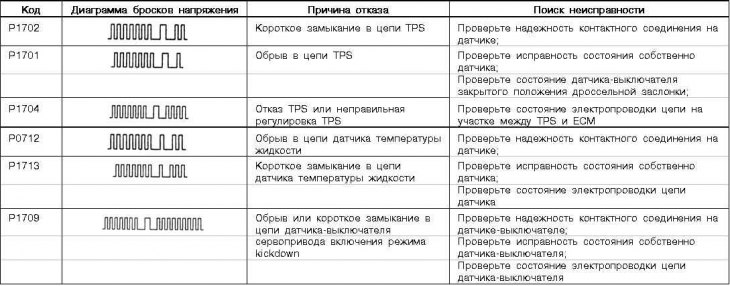
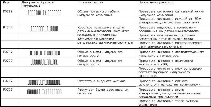
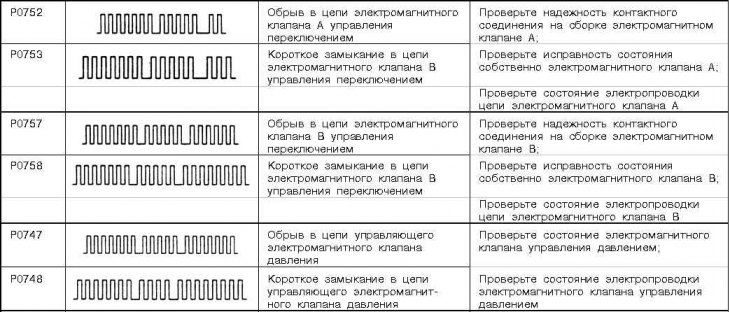
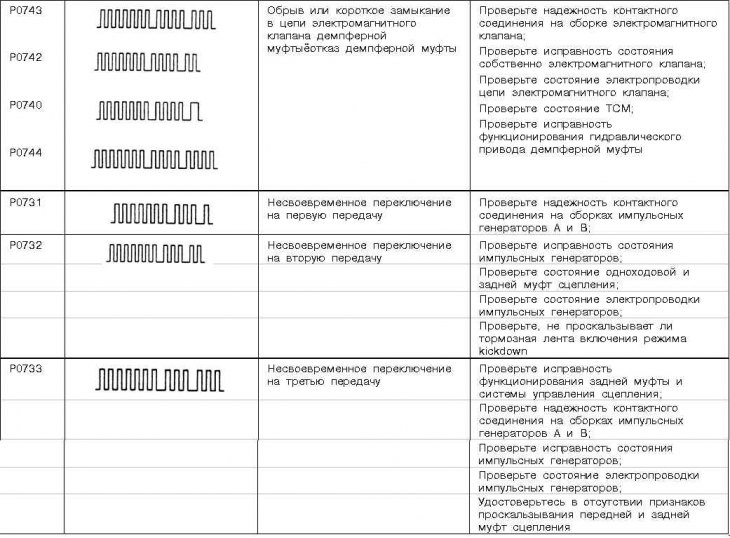

SRS security system trouble codes
The SRS control module includes a self-diagnosis unit. The fault codes recorded in the module memory are read by connecting a special scanner to the DLC diagnostic connector.
Note. The module memory is cleared using the same scanner.
Below is a list of the most common SRS failure codes.
| code no | Source and possible reason for failure |
| 11 | Short to ground in the front directional g-force sensor circuit; |
| SRS control module malfunction | |
| 12 | Open or short circuit in the chain of the front sensors of directional overloads; |
| SRS control module malfunction | |
| 13 | Open or short circuit in the chain of the front sensors of directional overloads; |
| SRS control module malfunction | |
| 14 | Malfunction of the sensor of directed overloads in the SRS control module |
| 15 | Short circuit in a chain of the control sensor of frontal overloads in the SRS module |
| 16 | Break in a chain of the control gauge of frontal overloads in the SRS module |
| 17 | Malfunction of the control sensor of lateral overloads in the SRS module |
| 21 | Short circuit in the driver's airbag module circuit (including drum cable connector) |
| 22 | Open circuit in the driver's airbag module circuit (including drum cable connector) |
| 24 | Short circuit in the passenger airbag module circuit |
| 25 | Open in the passenger airbag module circuit |
| 26 | Short circuit in the driver's seat belt emergency tensioner circuit |
| 27 | Break in the chain of the emergency tensioner of the driver's seat belt |
| 28 | Short circuit in the passenger seat belt emergency tensioner circuit |
| 29 | An open in the passenger seat belt emergency tensioner circuit |
| 31 | Malfunction of the capacitor of the sensor of frontal overloads in the SRS control module |
| 32 | Malfunction of the capacitor of the sensor of frontal overloads in the SRS control module |
| 33 | SRS control module crank signal; |
| Wiring fault | |
| 34 | Violation of the quality of contact connections in the circuit of the SRS control module |
| 35 | Writing an emergency collision signal to the memory of the SRS module |
| 41 | Excessively low supply voltage of the SRS module, - failure of the fuse, damage to the wiring; |
| Faulty SRS control module | |
| 42 | Excessively low supply voltage of the SRS module, - failure of the fuse, damage to the wiring; |
| Faulty SRS control module | |
| 43 | Failure of a control lamp SRS, - breakage of an electrical wiring (including bulb filament); |
| Malfunction of the SRS control module; | |
| Instrument panel malfunction | |
| 44 | Failure of a control lamp of SRS, - malfunction of the SRS control module |
| 45 | Malfunction of the control module SRS, - EEPROM |
| 46 | Malfunction in a chain of collisions of the SRS control module |
| 47 | Malfunction in the activator circuit of the driver's airbag, - a short circuit in the circuit of the SRS control module |
| 48 | Malfunction in the activator circuit of the driver's airbag, - open circuit in the control module circuit |
| 51 | Malfunction in the activator circuit of the driver's airbag, - a short circuit in the circuit of the SRS control module |
| 52 | Malfunction in the activator circuit of the driver's airbag, - open circuit in the control module circuit |
| 54 | Malfunction in a chain of an activator of a passenger pillow of safety, - short circuit in a chain of the SRS control module |
| 55 | Malfunction in a chain of an activator of a passenger pillow of safety, - break in a chain of the control module |
| 56 | Malfunction in a chain of the activator of an emergency pretensioner of a driver's seat belt, - short circuit in a chain of the SRS control module |
| 57 | Malfunction in the activator circuit of the emergency tensioner of the driver's seat belt, - open in the circuit of the SRS control module |
| 58 | Malfunction in a chain of the activator of an emergency pretensioner of a passenger seat belt, - short circuit in a chain of the SRS control module |
| 59 | Malfunction in a chain of the activator of an emergency pretensioner of a passenger seat belt, - break in a chain of the SRS control module |
| 61 | Short circuit on in a chain of a driver's pillow of safety, - malfunction of an electrical wiring or the SRS control module |
| 62 | Short to ground in the driver's airbag circuit, - wiring or SRS control module malfunction |
| 64 | Short circuit on in a chain of a passenger pillow of safety, - malfunction of an electrical wiring or the SRS control module |
| 65 | Short to ground in the passenger airbag circuit, - wiring or SRS control module malfunction |
| 66 | Short circuit on in a chain of a pretensioner of a driver's seat belt, - malfunction of an electrical wiring or the SRS control module |
| 67 | Short to ground in the driver's seat belt tensioner circuit, - wiring or SRS control module malfunction |
| 68 | Short circuit on in a chain of a pretensioner of a passenger seat belt, - malfunction of an electrical wiring or the SRS control module |
| 69 | Short to ground in the passenger seat belt pretensioner circuit, - wiring or SRS control module malfunction |
| 71 | Short circuit in the left side airbag circuit (except Galant models), - faulty wiring or SRS control module |
| 71 | Short circuit in the right side airbag circuit (Galant models), - faulty wiring or SRS control module |
| 72 | Open circuit in the left side airbag circuit (except Galant models), - faulty wiring or SRS control module |
| 72 | Open in the right side airbag circuit (Galant models), - faulty wiring or SRS control module |
| 73 | Failure of the activator of the left side airbag (except Galant models), - short circuit in the SRS control module circuit |
| 73 | Failure of the activator of the right side airbag (Galant models), - short circuit in the SRS control module circuit |
| 74 | Failure of the activator of the left side airbag (except Galant models), - open circuit in the SRS control module circuit |
| 74 | Failure of the activator of the right side airbag (Galant models), - open circuit in the SRS control module circuit |
| 75 | Short circuit in the left side airbag circuit (except Galant models), - faulty wiring or SRS control module |
| 75 | Short circuit in the right side airbag circuit (Galant models), - faulty wiring or SRS control module |
| 76 | Short to ground in left side airbag circuit (except Galant models), - faulty wiring or SRS control module |
| 76 | Short to ground in right side airbag circuit (Galant models), - faulty wiring or SRS control module |
| 79 | Violation of communication of the sensor of directional overloads of the left side airbag, - a malfunction of the wiring or the SRS control module |
| 81 | Short circuit in the right side airbag circuit (except Galant models), - faulty wiring or SRS control module |
| 81 | Short circuit in the left side airbag circuit (Galant models), - faulty wiring or SRS control module |
| 82 | Open in the right side airbag circuit (except Galant models), - faulty wiring or SRS control module |
| 82 | Open circuit in the left side airbag circuit (Galant models), - faulty wiring or SRS control module |
| 83 | Malfunction of the activator of the right side airbag (except Galant models), - short circuit in the SRS control module circuit |
| 83 | Malfunction of the activator of the left side airbag (Galant models), - short circuit in the SRS control module circuit |
| 84 | Malfunction of the activator of the right side airbag (except Galant models), - open circuit in the SRS control module circuit |
| 84 | Malfunction of the activator of the left side airbag (Galant models), - open circuit in the SRS control module circuit |
| 85 | Short circuit in the right side airbag circuit (except Galant models), - faulty wiring or SRS control module |
| 85 | Short circuit in the left side airbag circuit (Galant models), - faulty wiring or SRS control module |
| 86 | Short to ground in right side airbag circuit (except Galant models), - faulty wiring or SRS control module |
| 86 | Short to ground in left side airbag circuit (Galant models), - faulty wiring or SRS control module |
| 89 | Violation of communication of the sensor of directional overloads of the right side airbag, - a malfunction of the wiring or the SRS control module |
| 91 | Excessively low supply voltage of the sensor of directional overloads of the left side airbag, - malfunction of the sensor or SRS control module |
| 92 | Failure of the sensor of directed overloads of the left side airbag |
| 93 | Incorrect communication of the sensor of directional overloads of the left side airbag, - a malfunction of the wiring or the SRS control module |
| 94 | Excessively low supply voltage of the sensor of directional overloads of the right side airbag, - malfunction of the sensor or SRS control module |
| 95 | Failure of the sensor of directed overloads of the right side airbag |
| 96 | Incorrect communication of the sensor of directional overloads of the right side airbag, - malfunction of the wiring or control module |
