Attention! Due to the very high voltage generated in the ignition system, the maintenance of its components must be carried out with extreme care. This note applies not only to the main components of the electronic ignition system, but also to all related components, including spark plug wire tips, tachometer and other diagnostic equipment.
Contactless ignition systems with distributor
Checking the correctness of the HV voltage supply to the spark plugs
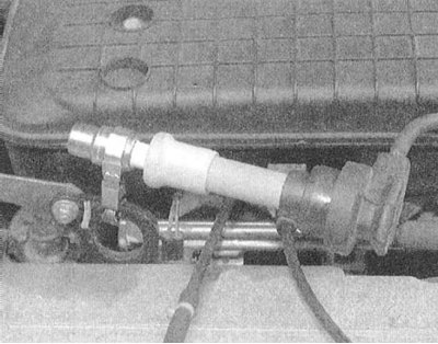
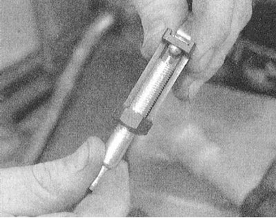
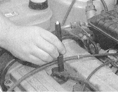
1. This test is best done with a special tester. There are currently three types of ignition testers in widespread use. The design of the first of them is based on the inductive principle of operation of a neon lamp; the device is simply pressed against the spark plug wire and the regular flashing of the lamp confirms the correctness of the voltage supply to the corresponding spark plug. Testers are available with an adjustable air gap to match the performance of the spark plug. Another tester looks like a spark plug, equipped with a ground terminal on the side, but without a side electrode. Testers of the last two types allow not only to check the correctness of the voltage supply to the HV plug, but also (flash color) evaluate the intensity of sparking - a weak spark is distinguished by a yellow-orange color, a strong spark is blue.
 |  |
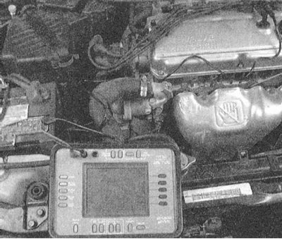
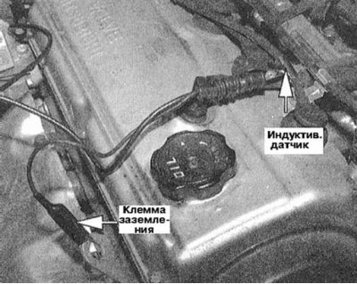
2. Professionals usually use an oscilloscope for this test, one of the working wires of which is equipped with an inductive sensor connected to the BB wire, the second with a terminal that allows the device to be grounded to ground.
 |  |
3. Disconnect the wire from the spark plug and connect it to the tester. Ground the instrument to the mass of the power unit.
Note. When using a tester with a neon indicator, there is no need to disconnect the wiring. In the absence of a tester at hand, it is enough to pull the rubber cover of the tip of the spark plug wire up and bring the terminals to the engine ground at a distance of about 6 mm and observe the intensity of sparking.
4. Turning the engine, observe the spark formed between the terminals of the tester
5. The presence of a spark of bright blue color confirms the serviceability of the voltage supply to the BB plug.
6. In the absence of sparking, first of all, check the condition of the spark plug wire, then proceed to the diagnosis of individual components of the ignition system.
Identifying the Cylinder Responsible for Misfires
1. Select neutral gear (RKPP) / move the selector lever to position P (AT). Engage the parking brake.
2. Start the engine and leave it running at idle.
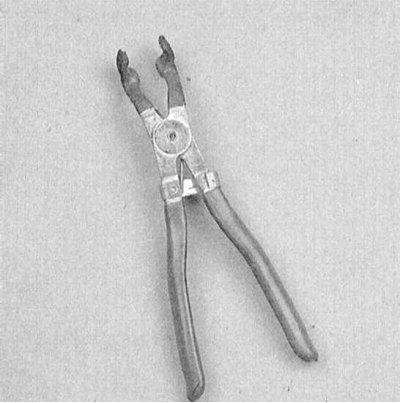
3. Begin to disconnect the wires from the spark plugs one by one, - the wire should be held by the tip, making rotational movements with it. To avoid electric shock, disconnect the BB wiring using special pliers with insulated handles. If disconnecting the wire leads to a violation of the stability of the engine speed, therefore, this cylinder is functioning properly, reconnect the wire in place and disconnect the next one. Continue checking until the defective cylinder is identified - when the wire is disconnected from its spark plug, there will be no visible change in the operation of the engine.
4. Stop the engine and check the condition of the BB wire and spark plug of the suspect cylinder. If necessary, diagnose other components of the ignition system (see below).
Adjustment
Non-contact ignition systems do not need any adjustments, except for setting the ignition timing. The description of procedure of adjustment of an angle of an advancing of ignition see in the Chapter Settings and ongoing maintenance.
Direct ignition systems (DIS)
Checks
Checks are carried out in the same way as described above for non-contact ignition systems.
Adjustment
DIS systems do not need any adjustments other than setting the ignition timing. The description of procedure of adjustment of an angle of an advancing of ignition see in the Chapter Settings and ongoing maintenance.
