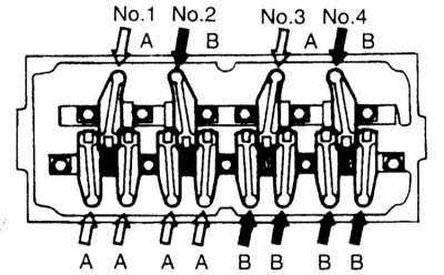
Note. Regular adjustment of valve clearances is carried out only on Mirage 1.5 l models 1990÷1995. issue and 1.8 l 1993÷1995 issue
Attention! Violation of the adjustment of valve clearances to an increase in the background noise produced by the valve mechanism and a violation of the stability of the engine speed. Checking and adjusting valve clearances must be carried out on an engine warmed up to normal operating temperature!
1. Warm up the engine to normal operating temperature, stop it and disconnect the negative cable from the battery.
Attention! If the stereo system installed in the car is equipped with a security code, before disconnecting the battery, make sure that you have the correct combination to activate the audio system!
2. For the purpose of simplification of cranking of the engine manually turn out spark plugs.
3. Remove the cylinder head cover.
4. Having turned the crankshaft clockwise, achieve the alignment of the installation risk on the pulley with the T mark on the lower cover of the timing belt, - the pistons of the 1st and 4th cylinders should be in the TDC positions. By moving the rocker arms of the valve drive of the 1st and 4th cylinders up and down, determine which piston of the cylinders occupies the TDC position of the end of the compression stroke (both rockers will move freely).

5. Using a blade-type feeler gauge, measure the valve clearances. In the TDC position of the end of the compression stroke of the piston of the 1st cylinder, the clearances of the intake and exhaust valves of the 1st and 2nd cylinders are measured. Then the crankshaft should be rotated one full turn clockwise to bring the end of the compression stroke of the 4th cylinder to TDC and measure the clearances of the intake and exhaust valves of the 3rd and 4th cylinders.
6. Compare the measurement results with the requirements of the Specifications. If necessary, loosen the locknut of the corresponding valve actuator rocker and adjust its clearance using the adjusting screw. Having achieved the desired result, tighten the lock nut with the required force (12÷15 N·m for 1.5 l models/9 N·m for 1.8 l models), - make sure that the position of the screw does not change during the tightening of the nut.
7. Replace the cylinder head cover, screw in the spark plugs and connect the negative cable to the battery.
