Disassembly
Reverse Idler Shaft
1. Shift the 3/4th gear synchronizer clutch to 4th gear (pic. 11.73).
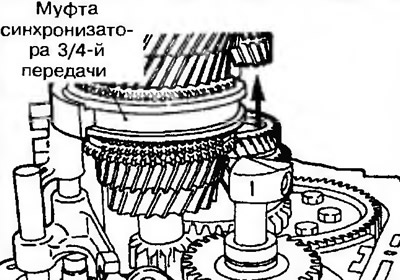
Pic. 11.73. Removing the reverse gear shaft
3rd and 4th shift fork stem, 3rd and 4th shift fork, 5th shift fork, circlip, reverse clutch cam, 5th shift clutch stem, steel ball and rod of blocking of inclusion of a transfer of a backing.
2. Move the reverse clutch cam in the direction of the arrow and remove the 5th shift fork, 5th shift fork stem, reverse clutch cam, circlip, steel ball, and shift lock rod reversing (pic. 11.74).
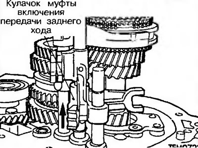
Pic. 11.74. Move the reverse clutch cam in the direction of the arrow and remove the 5th shift fork, 5th shift fork stem, reverse clutch cam, circlip, steel ball and reverse shift lockout stem
3. Move the 3rd and 4th shift fork stem in the direction of the arrow and remove the stem together with the shift fork (pic. 11.75).
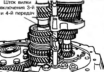
Pic. 11.75. Move the 3rd and 4th shift fork stem in the direction of the arrow and remove the stem together with the shift fork
Primary and secondary shafts
4. Primary and secondary shaft are removed together (pic. 11.76).
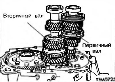
Pic. 11.76. Removing the primary and secondary shafts
Adjustment before assembly
The choice of an adjusting washer for adjusting the axial clearance of the differential
5. Install the gauge wire (10 mm long, 1.6 mm in diameter) on the gearbox housing and install the differential as shown in fig. 10.77.
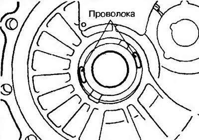
Pic. 11.77. Install the gauge wire (10 mm long, 1.6 mm in diameter) on the gearbox housing and install the differential
6. Install the clutch housing and tighten the bolts to the required torque.
7. If the gauge wire does not compress, install another with a larger diameter and repeat steps 1 and 2.
8. Measure the thickness T of the compressed gauge wire with a micrometer (pic. 11.78). Select a shim. Thickness of an adjusting washer: from T - 0.05 mm, to T - 0.17 mm.
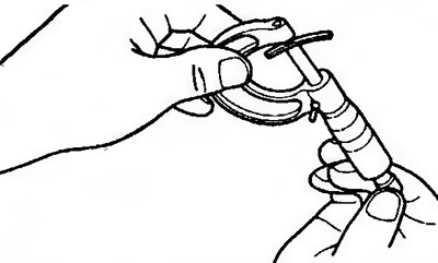
Pic. 11.78. Measure the thickness T of the compressed gauge wire with a micrometer and select a shim
Assembly
3rd and 4th shift fork stem, 3rd and 4th shift fork, 5th shift fork, circlip, reverse clutch cam, 5th shift clutch stem, steel ball and rod of blocking of inclusion of a transfer of a backing.
9. Install the 3rd and 4th shift fork shaft and the 3rd and 4th shift fork (pic. 11.79).
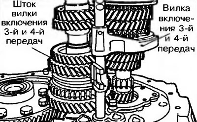
Pic. 11.79. Install the 3rd and 4th shift fork shaft and the 3rd and 4th shift fork
10. Assemble reverse gear lock rod 1, steel inner ball 2, 5th shift fork stem 3, 5th shift fork 4, reverse shift clutch cam 5, circlip 6 (pic. 11.80, a, b).
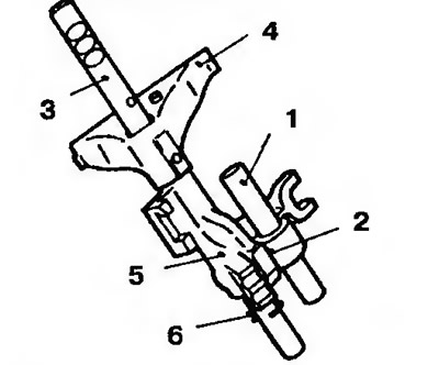
Pic. 11.80a. Correct installation of reverse gear lock rod 1, steel inner ball 2, 5th gear shift fork stem 3, 5th gear shift fork 4, reverse gear shift clutch cam 5, circlip 6 | 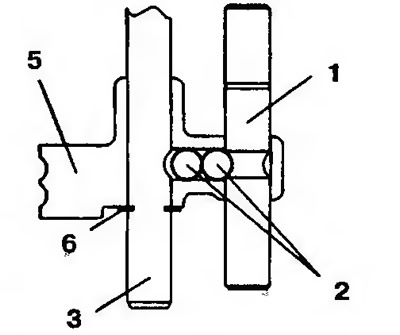
Pic. 11.806. Correct installation of reverse gear lock rod 1, steel balls 2, 5th gear shift fork stem 3, reverse gear clutch cam 5, circlip 6 |
11. Move the reverse clutch cam in the direction of the arrow (pic. 11.74). Install the 5th shift fork and stem, reverse clutch cam, circlip, steel ball and reverse shift lockout stem.
Reverse Idler Shaft
12. Shift the 3rd and 4th gear synchronizer clutch to 4th gear (pic. 11.73).
13. Position the threaded hole of the reverse idle gear shaft in the direction shown in fig. 11.81.
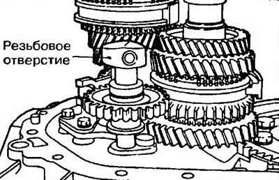
Pic. 11.81. Correct location of the threaded hole of the shaft of the intermediate gear of the reverse gear
