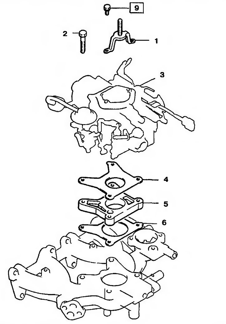
Pic. 10.35a. Carburetor assembly: 1 - Hairpin; 2 - Bolt; 3 - Carburetor; 4 - Top gasket; 5 - Rubber cushion; 6 - Bottom gasket

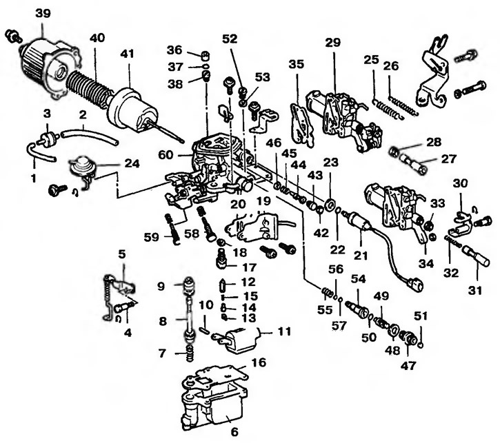
Pic. 10.356. Disassembled carburetor: 1, 2 - Tubes (automatic transmission); 3 - Deceleration valve (automatic transmission); 4 - Bolt; 5 - Pump lever; 6 - Float chamber; 7, 15, 32, 45, 55 - Springs; 8 - Pump piston; 9, 22, 28, 33, 37, 50, 56, 57 - Seals; 10 - Pin; 11 - float; 12 - Needle valve; 13 - Hook; 14 - Push pin; 16, 18, 20, 23, 35, 46, 48, 53 - Gaskets; 17 - Needle valve seat; 19 - Adapter; 21 - Solenoid valve for cutting off the fuel supply; 24 - Throttle valve closing actuator (automatic transmission); 25 - Return spring (outdoor); 26 - Return spring (internal); 27, 31 - Economizer drive rods; 29 - Compensator; 30 - Eccentric to increase the engine speed; 34 - Compensator; 36 - Locking plate; 38, 52 - Pins; 39 - Diffuser; 40 - Diffuser spring; 41 - Diffuser piston; 42 - Plug (for Australia); 43 - Screw for regulating the composition of the combustible mixture (MAS); 44 - Hairpin; 47 - Threaded plug of the main fuel jet; 49 - Adjusting screw of the main fuel jet; 51 - Locking plate; 54 - Main fuel jet; 58 - Speed adjusting screw (SAS); 59 - Throttle valve actuator adjusting screw (automatic transmission); 60 - Carburetor body
