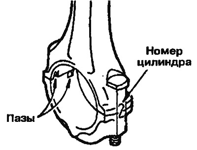
Pic. 2.43. Marking on the connecting rod
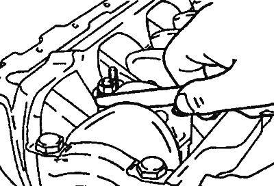
2. Please note that the side clearance does not exceed the allowable value (pic. 2.44).
- Normal value: 0.10-0.25mm.
- Permissible value: 0.4 mm.

Pic. 2.44. Checking the backlash in the connecting rod bearing cap
