Removing
1. Remove the timing belt and camshaft sprocket.
2. Remove the oil pan.
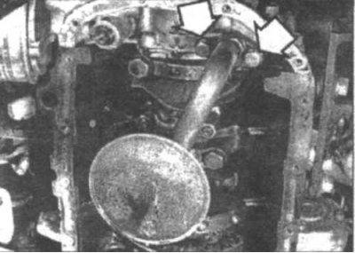
14.3 The oil pickup pipe is attached with two bolts (indicated by arrows) to the back of the oil pump (1.5 l)
3. Remove the oil pickup bolts from the back of the oil pump (14.3).
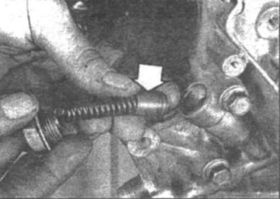
14.4 Unscrew the pressure regulator plug, remove the spring and plunger
4. Unscrew the pressure regulator plug, remove the spring and plunger (14.4).
5. Remove the timing belt tensioner.
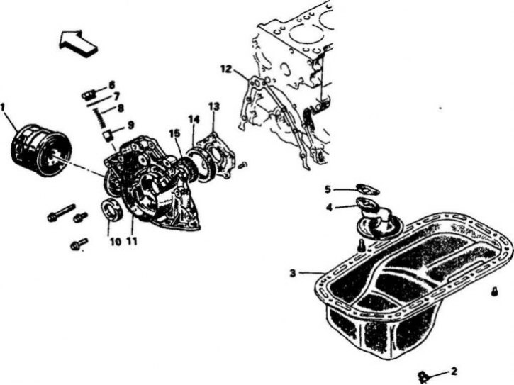
14.6a Oil pump (1.5 l)
1. Oil filter; 2. Drain plug; 3. Oil pan; 4. Oil intake pipe; 5. Gasket; 6. Plug; 7. Pressure regulator spring; 8. Pressure regulator plunger; 10. Front crankshaft oil seal; 11. Pump casing; 12. Gasket; 13. Oil pump cover; 14. External gear; 15. Internal gear
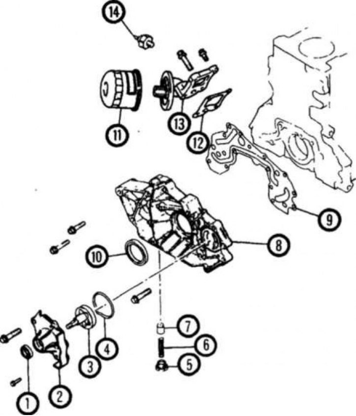
14.6b Oil pump (1.6 l)
1. Oil seal; 2. Oil pump cover; 3. Oil pump rotor; 4. Gasket; 5. Plug; 6. Spring; 7. Plunger; 8. Casing; 9. Gasket; 10. Crankshaft oil seal; 11. Oil filter; 12. Gasket; 13. Oil filter adapter; 14. Oil pressure switch
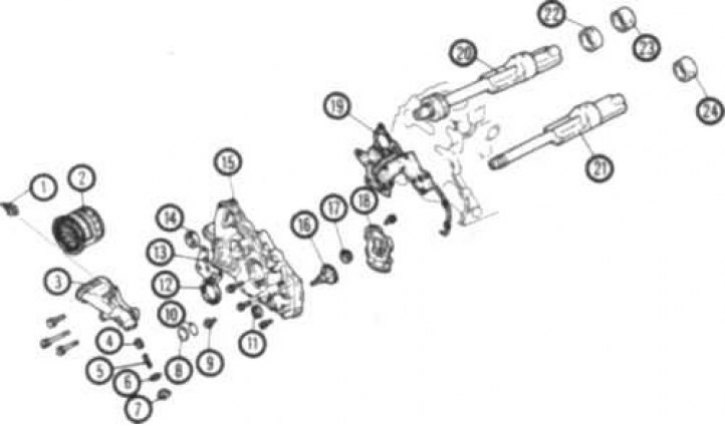
14.6v Oil pump (2.0L SOHC and DOHC, 2.4L and 1.8L)
1. Oil pressure switch; 2. Oil filter; 3. Oil filter bracket 4. Plunger; 5. Spring; 6. Gasket; 7. Plug; 8. Plug cover '9. Bolt; 10. O-ring; 11. Silent shaft seal; 12. Front crankshaft oil seal; 13. Gasket; 14.Gland; 15. Casing; 16. Oil pump drive gear; 17. Oil pump driven gear; 18. Oil pump cover; 19. Gasket; 20. Right silent shaft; 21. Left silent shaft; 22. Silent shaft front bearing; 23. Rear bearing of the right silent shaft; 24. Rear bearing of the left silent shaft
6. Unscrew the bolts securing the oil pump to the cylinder block. Carefully remove the pump from the engine (14.6a, 14.6b, 14.6c).
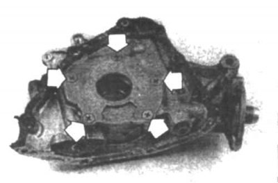
14.7 Remove the screws (indicated by arrows) and remove the oil pump cover (1.5 l)
7. Remove the cover from the back of the casing (14.7) and remove the pump inner and outer gears.
8. Remove the crankshaft oil seal from the casing.
Examination
9. Thoroughly clean all parts and remove traces of the old gasket from the surfaces. Inspect parts for wear, cracks or other damage. Replace if necessary.
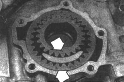
14.10a Install the inner and outer gears so that the marks are located as shown in the figure (1.5 l)
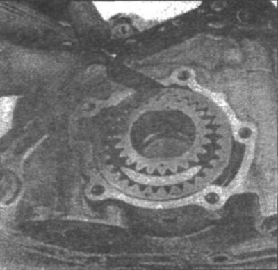
14.10b Measure the gap between the outer gear and the pump casing
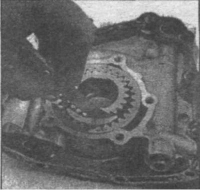
14.10c Measure the clearance between the inner gear and the spacer.
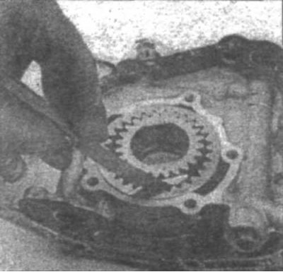
14.10g Measure the clearance between the outer gear and spacer.
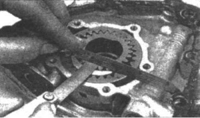
14.10e Measure the clearance between the side planes of the gears and the plane of the pump housing
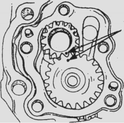
14.10e In gear-type pumps driven by a timing belt, install the gears by aligning the marks
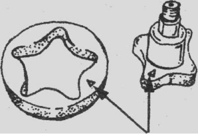
14.10g In a rotary pump, install the rotor so that the marks are facing up
10. Install the pump inner and outer gears and measure the clearances (14.10a, 14.10b, 14.10c, 14.10d, 14.10d, 14.10e, 14.10g). Measure the length of the pressure regulator spring. Compare the values you obtained with the data given in the Technical Specifications.
Replace parts if necessary. Install the pump cover. Tighten the bolts.
Installation
11. Install a new crankshaft oil seal.
12. Install the pressure regulator parts and screw on the plug.
13. Install pump and new gasket, insert and tighten bolts.
14. Install the remaining parts.
15. Fill with oil, start the engine and check the oil pressure.
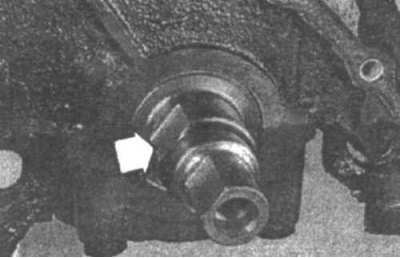
14.13 When installing the pump, remember that the inner toothed ring must fit on the flat cut of the crankshaft
